The add-on system
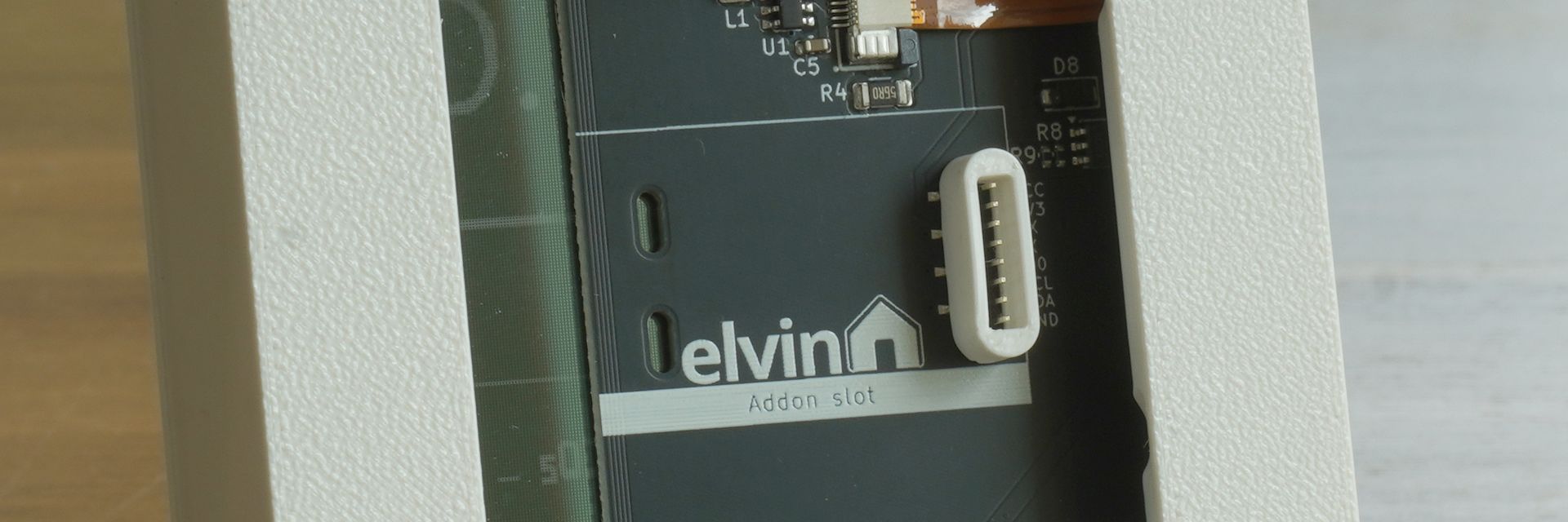
On the back of the CTRL ONE sits a standard 8-pin header that lets you extend the device. Official add-ons such as the thermostat, buzzer and breakout board plug straight in, and with a bit of ESPHome configuration you can drive hardware of your own design.
The header exposes a single general-purpose GPIO, an I2C bus, a UART, and power - enough for most sensors and simple actuators. It uses a standard connector with a fine 1.27 mm pitch, making it easy to design your own add-on boards. The connector has a shroud placed around it to prevent plugging in the add-on board incorrectly.
What add-on do I need?
Using the CTRL ONE on USB-C power with its built-in sensors does not require an add-on at all. Add-ons are for when you want to power the device differently or add extra hardware:
You want to... | Use this add-on |
|---|---|
Power a wall-mounted device from your heating system's 24 V AC wiring and control it as a thermostat | |
Power the device from an external DC supply (5 - 28 V), or wire up your own sensors and components | |
Add sound notifications and alerts |
Signals
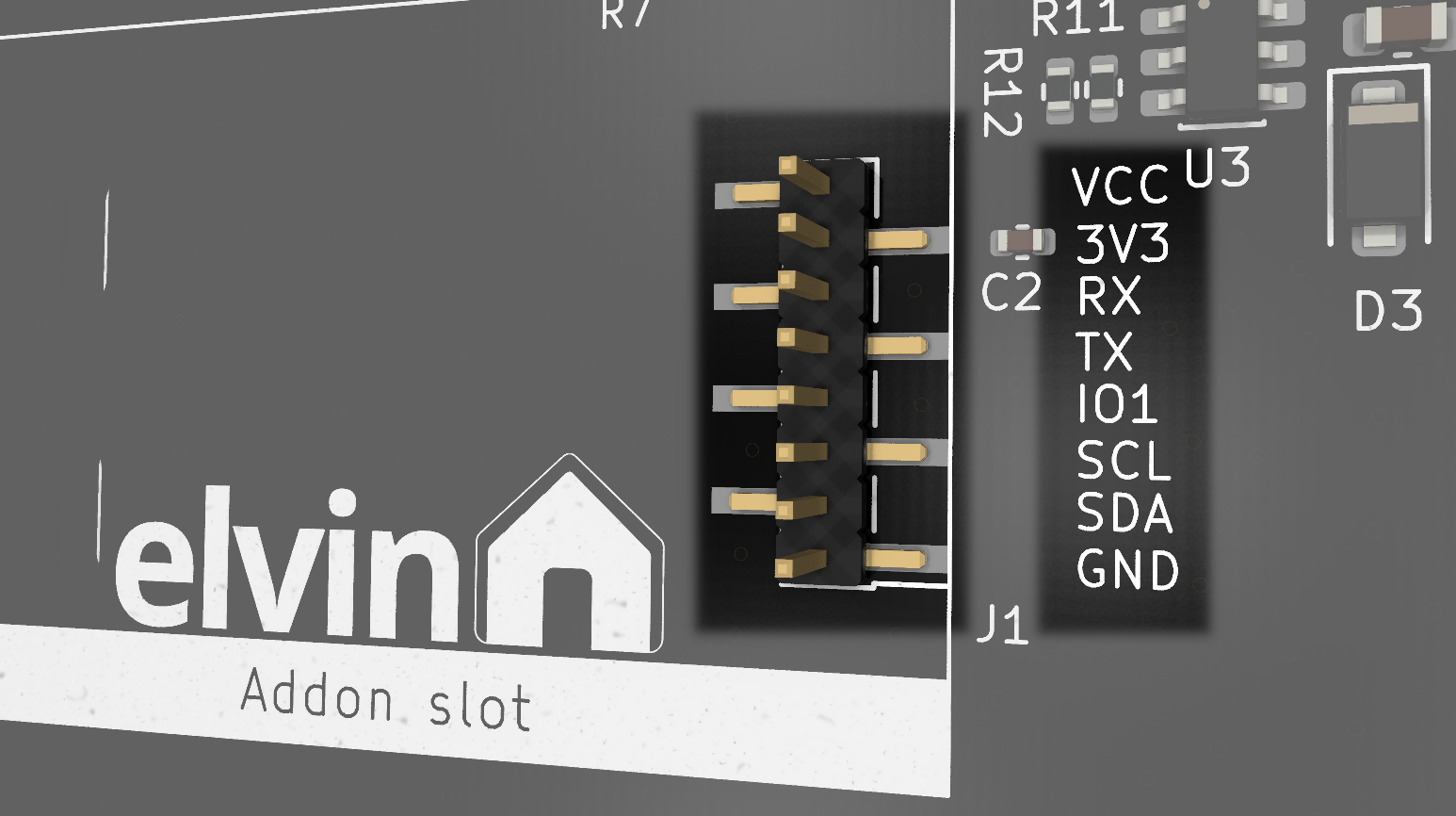
A render of the PCB and markings showing the location of each pin. Connector shroud not shown.
Signal | ESP32 pin | Direction | Purpose |
|---|---|---|---|
3.3 V | - | Output | Power for low-power connected sensors |
VCC | - | Input | 5 V - 28 V DC power input (see the power section below) |
GND | - | - | Common ground |
SDA | GPIO3 | I/O | I2C data line |
SCL | GPIO2 | Output | I2C clock line |
GPIO1 | GPIO1 | I/O | General-purpose add-on I/O (see below) |
RX | GPIO17 | Input | UART receive |
TX | GPIO16 | Output | UART transmit |
The I2C bus (the SDA and SCL pins) runs at 100 kHz and is shared with the onboard SCD40 sensor, along with the touchscreen interface.
The GPIO1 line is the one add-on I/O pin that is freely available. The RX and TX pins are not used out of the box, so they can also be repurposed for general IO.
Power
The VCC line accepts 5 V to 28 V DC, so an external power supply can power the CTRL ONE through the add-on slot. The 3.3 V line can be used either as a power input, or output for connected low-power sensors.
Do not use the USB port while the device is powered through the add-on slot.
Building your own add-on
The breakout add-on converts the fine-pitch connector to standard 2.54 mm pins, which is the easiest way to prototype. Once you have a design that works, you can build a custom board that mates directly with the 1.27 mm header. Your add-on appears to the firmware as the I2C bus and the GPIO1 line, both of which are configured in the ESPHome YAML - see the ESPHome configuration page.
Note: Early revision CTRL ONEs in the first batch have a misprint on the add-on slot: the GPIO1 line is labelled IO0 on the PCB. It is GPIO1 on the ESP32, as stated in this documentation. The misprint does not affect functionality. It is corrected in future batches.