
My workshop has been looking like a dungeon for a few weeks now. With a small painter's light sitting in the corner, the space has been a metal chair and few zip-ties away from the dream of every kidnapper depicted in a Hollywood blockbuster. Okay, maybe I'm exaggerating, but the point I'm trying to make is... lighting makes a huge difference to a space, and I wanted a solution that directed it right to where I need it most; the worktop where I work.
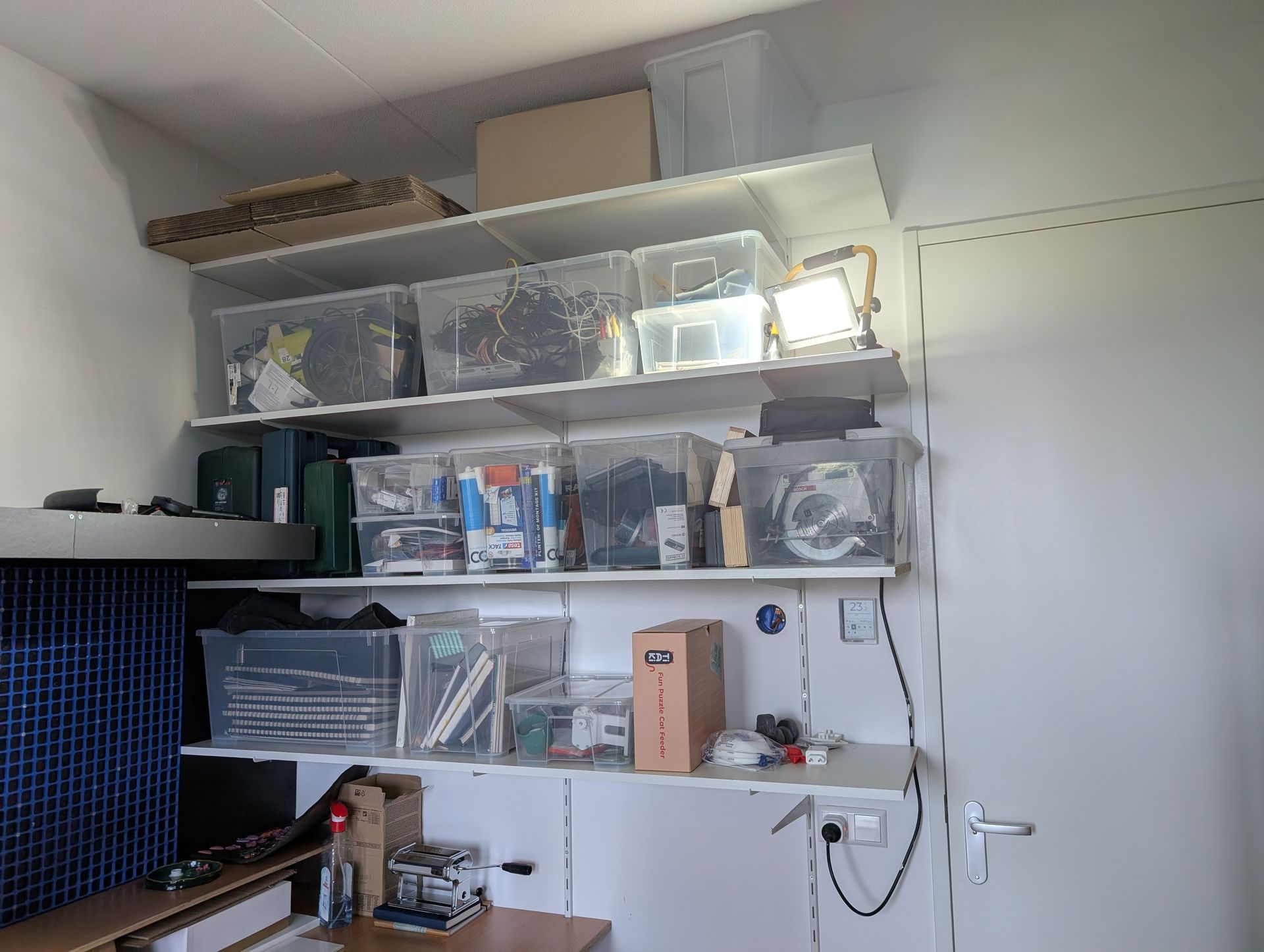
Now don't get me wrong, that painter's light is super bright and is generally fine for human eyes, but they have one major Achilles’ heal; they flicker at a relatively low frequency. Since I tend to make a lot of videos in my workshop, that flickering has been showing up on camera a bit.
By making one continuous strip of light all the way along the surface, I can solve not just the flickering issue, but I also have a solid source of light for anything I film here. As the workshop is split into 3 workstations, I needed a design that would allow me to adjust the color temperature and brightness for each of the 3 zones independently, and for that I was going to need to build something custom.
Every project is a chance for me to learn something new the hard way, and share those learnings with you. This was my first project where I designed my own buck converter to convert the 24V power to the 3.3V the microcontroller expects, and speaking of microcontrollers, this is also my first time using the ESP32-C6-MINI, a relatively new form factor of ESP32 that's super small, having everything you need and nothing you don't.
The shelf itself
I'm going to keep this part brief, as lingering here for too long may shine a spotlight onto my pretty mid carpentry skills. I blame my tools. Check out the video above to get an idea of how it fits together. Essentially it's a floating shelf design, using some standard wood pieces to create a frame that then has some laminated chipboard pieces screwed into the top and bottom. I'm not very confident in how much weight this design can support, but it was never designed for storage. It needs to hold itself, and a few plants. There's a reason why the floating shelves you buy from IKEA have a metal inner support structure.
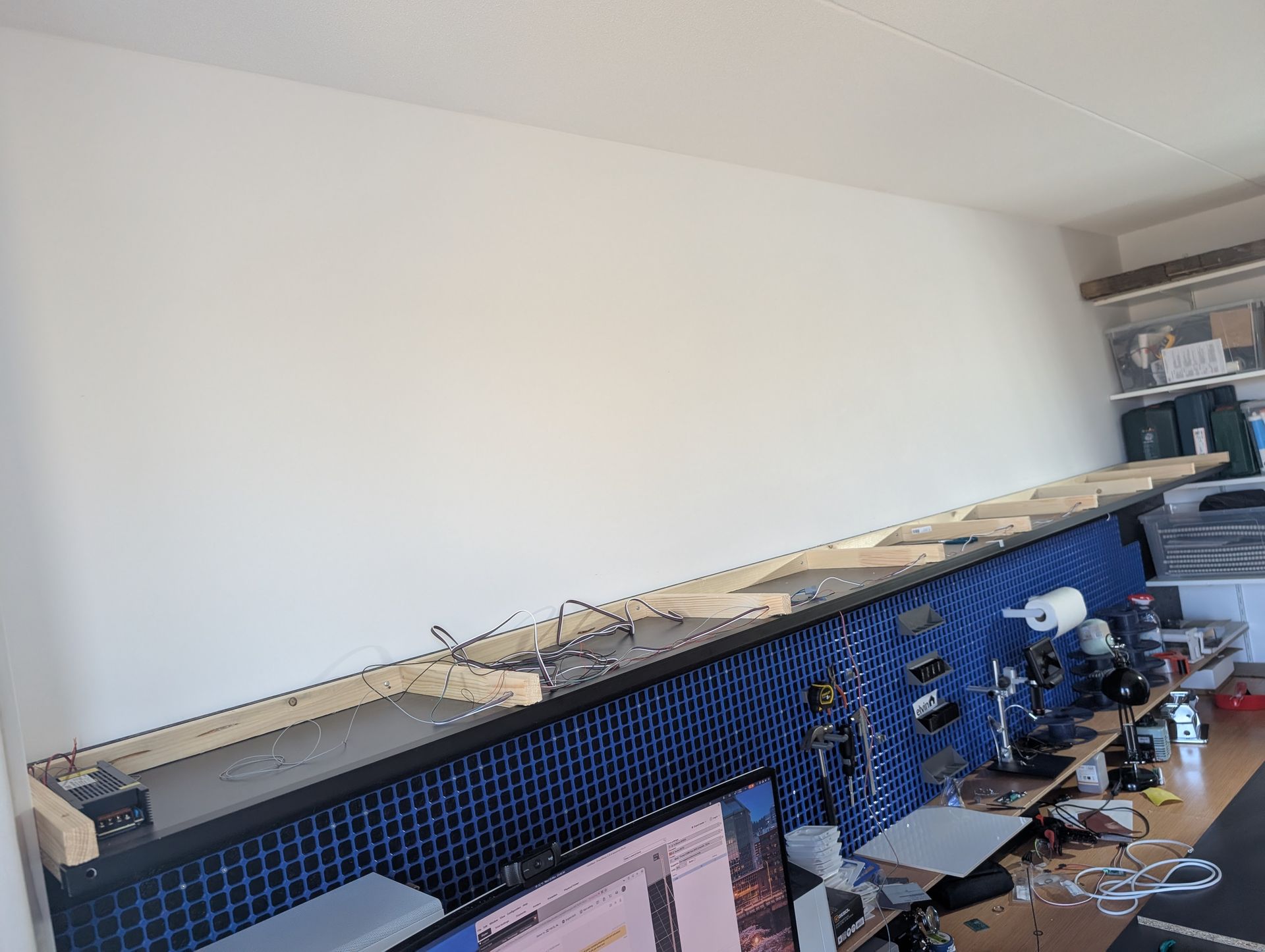
As it's a super long space, it was split into two pieces - basically the maximum length I could fit into the car. Additionally, the top section of the shelf is just sitting there, so I can easily lift it up and get to the PCB and power supply housed on the left side. There's plenty of leftover space in there, I wonder what else I could hide....
Hiding the lighting
To house the lighting, I bought this LED profile from ClarumLED. It has a 3cm width internally, which I chose so I could stuff it full of LEDs. I wanted this this to be bright, and it achieves that goal nicely. One major issue with using LED strips is cheap ones especially never get that bright, mainly due to the challenges in getting the heat away from the LEDs. While the Auxmer LED strips I'm using score a 10/10 for me in looks and reliability, I knew that I'd need to double them up to get a high brightness across the entire space.
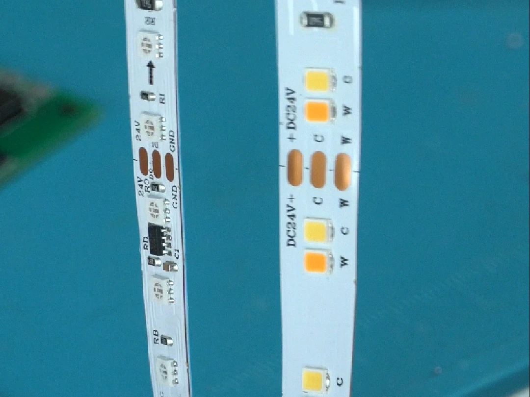
But at 1cm each, it meant I still had room for one more strip if I wanted... but as I run the entire setup at 24V, that limits the options somewhat for addressable RGB LED strips. The majority you find online run at 12V. After a little bit of searching, I stumbled across this strip from BTF lighting.
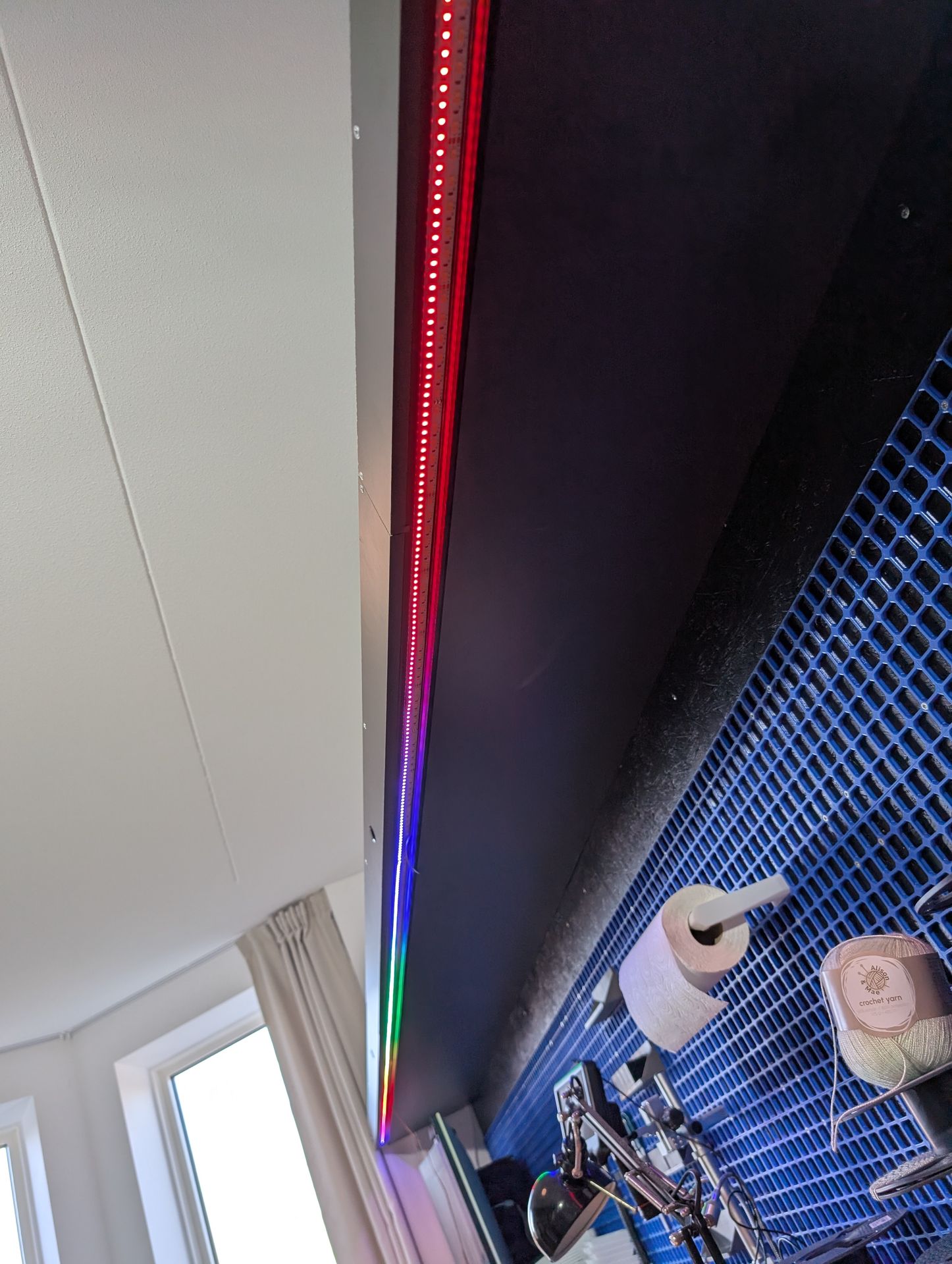
It's absolutely perfect for my needs, but it does actually come with one small caveat; from what I can tell, all addressable LEDs on the market expect 12V or less. For this strip to run at 24V, it actually uses a set of regular RGB LEDs, with a separate addressable LED controller. To keep things reasonable, what this actually means is that they are only addressable in groups of 6 LEDs. Ultimately this worked out just fine for my use case, as the LED profile is quite deep and the milky white diffuser blends the transition between each group well. It is something to keep in mind in smaller installations though.
The sad reality is that LED strips are just not the most efficient form of LED lighting. You can have the most efficient LED chips in the world, but as the voltage of the LEDs don't cleanly divide into the 24V supply, manufacturers use a lot of resistors to drop the remaining voltage. This turns a significant percentage of energy - in my case around 25% (!!) - directly into waste heat. When running at 100%, the outside of the LED profile is uncomfortable to touch. What they lack in efficiency, they make up in cost and ease of use, and I can't think of any other way I'd be able to easily create a 4 meter long light bar.
The brains of the operation
The combination of "dumb" warm white/cold white LED strips and the much smarter addressable RGB strip requires a custom setup to run it. Here's the list of requirements:
- We have 3 independent lighting zones, each with two different color channels. Therefore we need 6 independent PWM (Pulse Width Modulation) generators to generate a dimmable signal for each channel.
- The addressable RGB strip uses the WS2811 protocol, while it is powered using 24V, the logic line runs on 5V. So I need to generate a signal at that voltage.
- There are 3 buttons that need to turn on and off their respective zones, and they are momentary switches as the lights can also be changed via Home Assistant.
- The left-hand button also has an integrated LED ring, so it can flash and show the status, for example if we lose WiFi.
For this, I chose the ESP32-C6. It supports the latest WiFi standards and is relatively cheap. One gotcha I've had in previous projects is that while the original ESP32 supports up to 8 PWM channels, the C6 and others only support 6. For my usecase of 6 channels needed for 3 lighting zones, this runs it to its max, and will suit it just fine. We'll use that signal to control a set of N-Channel MOSFETs, which will do the work of actually controlling the power to the LED strip.
Next up is the addressable RGB strip. An ESP32 uses 3.3V, and therefore is unable to generate a 5V signal. We'll need to have a way to convert that 3.3V signal into 5V. If you're lucky, some addressable strips will work (just barely) with a 3.3V strip, but no dice with mine. Trying that resulted in a very flickery mess. There's one more consideration to make though - even when the addressable strip is "turned off", each of those WS2811 controllers across the entire strip are using a small amount of power, listening for their next command. By adding a 7th N-Channel MOSFET on the power line of the strip, it can be entirely powered off when it's doing nothing.
I'm not one for custom coding up an entire firmware for something like this even in the age of vibe-coding, and I don't have to. There are two ESP32-focused projects out there WLED and ESPHome. At first WLED seemed like a natural fit for this project as it's all to do with lighting, and it's able to do all sorts of fun lighting effects along the addressable RGB strip. But let's be real; that RGB strip is just for the bling factor. For day to day usage, I'm just choosing the colour temperature of my white light. I'm much more well-versed in the use of ESPHome, and as I'm pretty security-conscious, I much prefer having a device that is compiled with only what I need (I don't need a web interface for it, I use Home Assistant for that) and it allows API encryption. I opted for this as it just gave me everything I needed with nothing I don't. I've included the ESPHome configuration at the bottom of this post, if you're looking for some inspiration.
Finally, the buttons - that's pretty simple, expose some GPIO and connect it directly. The LED ring happily lights up on 3.3V and is a simple indicator, so a GPIO on the ESP32 will power it directly.
Building the PCB
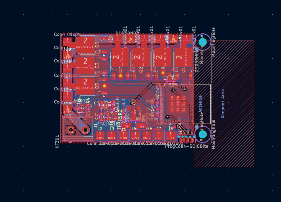
There's quite a big jump between the ESP32 development boards you can pick up off many hobbyist websites, and the ESP32-C6-MINI-1 module I am using for this project. So why bother to use it? This was actually a learning experience for integrating an ESP32 into the CTRL ONE, which I'll be selling soon on my store. I needed some hands-on experience on using something that is designed to be production-grade, and boy did I learn some things the hard way.
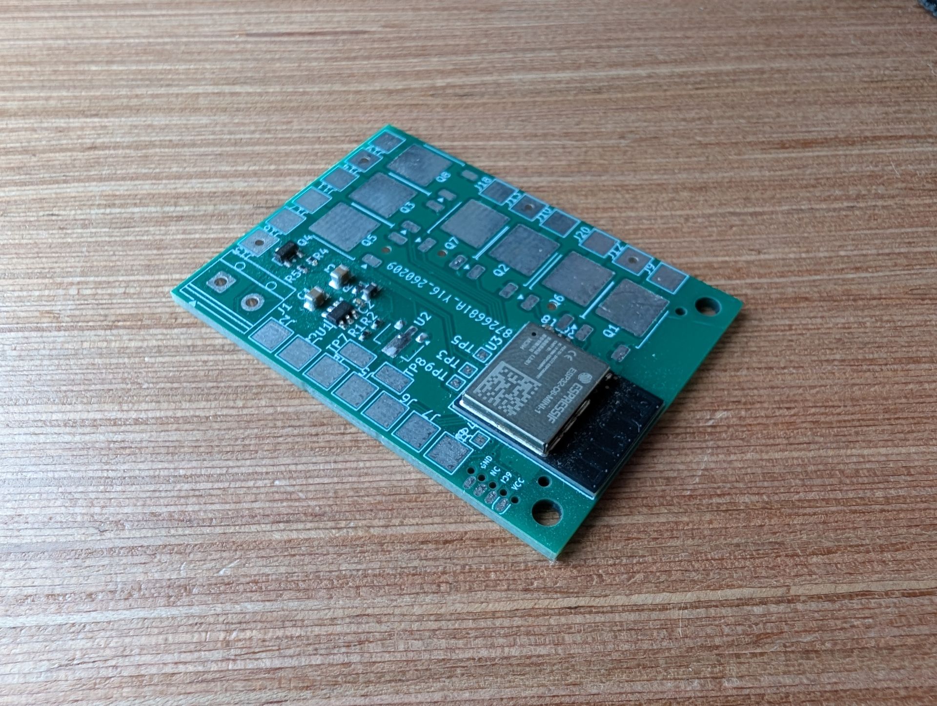
Most dev boards come with a nice USB port, accepting 5V power. They then have circuitry onboard that converts the 5V to the 3.3V that the ESP32 is expecting. Not only does this make it simple to power them from USB, but the 5V is always exposed so you can use it elsewhere.
The ESP32-C6-MINI has none of that. It accepts 3.3V and expects you to figure out the rest. That works fine for me because I need to build a regulator to step down from 24V, but how am I going to get the 5V for the addressable RGB strip?
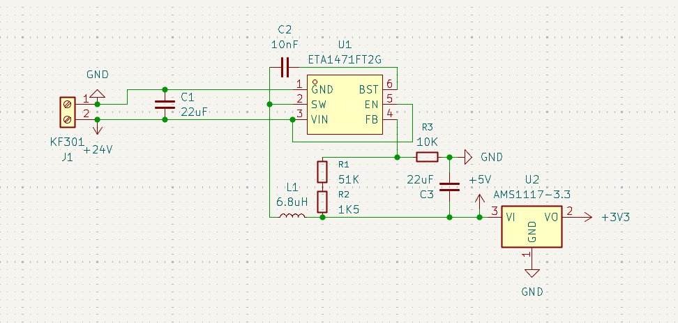
If you squint hard enough, it looks like an acceptable schematic. I've learned a lot since this first design!
In the end I designed a buck converter that takes 24V, and turns it into 5V. I then used a Linear Regulator to go from 5V to 3.3V. Linear regulators are super simple as they're just one component, but they do their conversion by letting off the voltage as waste heat, making them very inefficient. It was a lot more cost effective than trying to build 2 buck converters, one for each power level.
I'll save you the trouble here - if you're building a one-off project, I would not recommend these mini modules. They use a LGA (Land Grid Array) meaning that the pads are on the bottom, making them impossible to hand solder and taking some skill and patience to get it right with a reflow oven. I used JLCPCB's assembly service for this, and they charge a little extra to take an x-ray of the assembled board, to ensure that there's no soldering issues. As mentioned, I only went this route as I was learning how to use these in production.
Rookie mistakes
After designing the PCB, I waited patiently for a few weeks, and it finally arrived! Not without some extra cost - in previous projects I've used JLCPCB's "Economic" assembly service. If you stick to the standard parts that they mark as "basic" there are no extra fees for loading it into the pick & place machine, so if you're smart about it, you can get one-off projects for really cheap.
Unfortunately, any component using BGA or LGA like the ESP32-C6-MINI is not eligible for economic PCB assembly, meaning I had to use the standard service. The fee per component loaded is lower, but you don't get the benefit of no loading fees for basic parts, so it worked out quite a bit more expensive for me.
So why am I talking so much about LGA? Oh, the pains did not end here. It's pretty standard practice for any newly designed PCB to come with some... flaws (mistakes). And most of the time, you can just bodge a.k.a manually add a wire across the affected section to fix it. Not here.
I forgot to connect the EN pin to anything. Let's just go check the Espressif documentation on that one.
Name | No. | Function |
EN | 8 | High: on, enables the chip. Low: off, the chip powers off. Note: Do not leave the EN pin floating. |
That sounds pretty important. And leaving it floating i.e. not connecting it is exactly what I did. And that's when it hit me... all the dev boards had sorted that for me. By default they pull the pin high, to ensure that the ESP32 turns on. By not doing this, the chip essentially just was not turning on.
So just run a wire right? Nope, that EN pin is on a pad on the underside of that chip. I've now learned the hard way that it's good practise on prototype boards to run a trace out from every pad, instead of just being way too confident. Because if you make a mistake, you then at least have a way to tap into that line and manually fix it.
Back to JLCPCB for me.
Round 2
A few weeks later, with the new board in hand and issues fixed, the tests went great! I'm now using a super cool little design called SOICBite, which adds a few small contacts on the side of the board that you can connect a programmer to. There's no need to add an entire USB port to something that will hopefully be flashed once and permanently installed, so this is a no-cost way of adding in programming functionality.
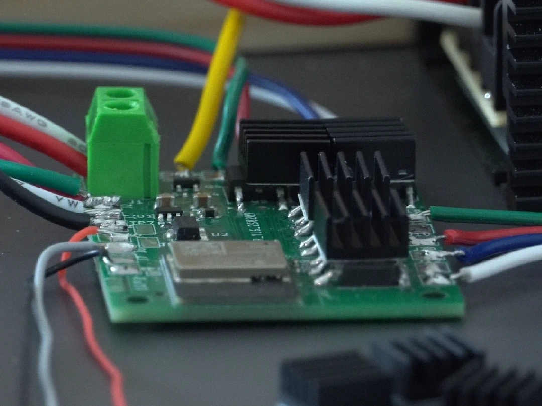
With that, it was time to install it into its final home. This is the most power I've put through a homemade board before, so I ended up installing some little heatsinks on top of the MOSFETs as they were running a little too hot. I'm using a 300W power supply from SANPU, the same brand I've used to power every other one of my projects, and I've made sure to over-spec this one by quite a lot as it will be sitting inside the shelf, with very little ventilation.
I've now been running this for a few months and the power draw when maxed out is just over 150W, but the heat has not been too much an issue. The RGB is definitely a fun party trick to pull in the evenings, but overall the MOSFET to control the power to that strip was a wise choice because it does not get used often.
With this project done, I consider my workshop to be ready to roll. This will be the space where every CTRL ONE is built and shipped, and with proper lighting in place, I'll be able to make sure that every unit leaves here looking just the way I intended. It also shines a big light on the mess that I make in this workshop every day, but that's just the signs of productivity!
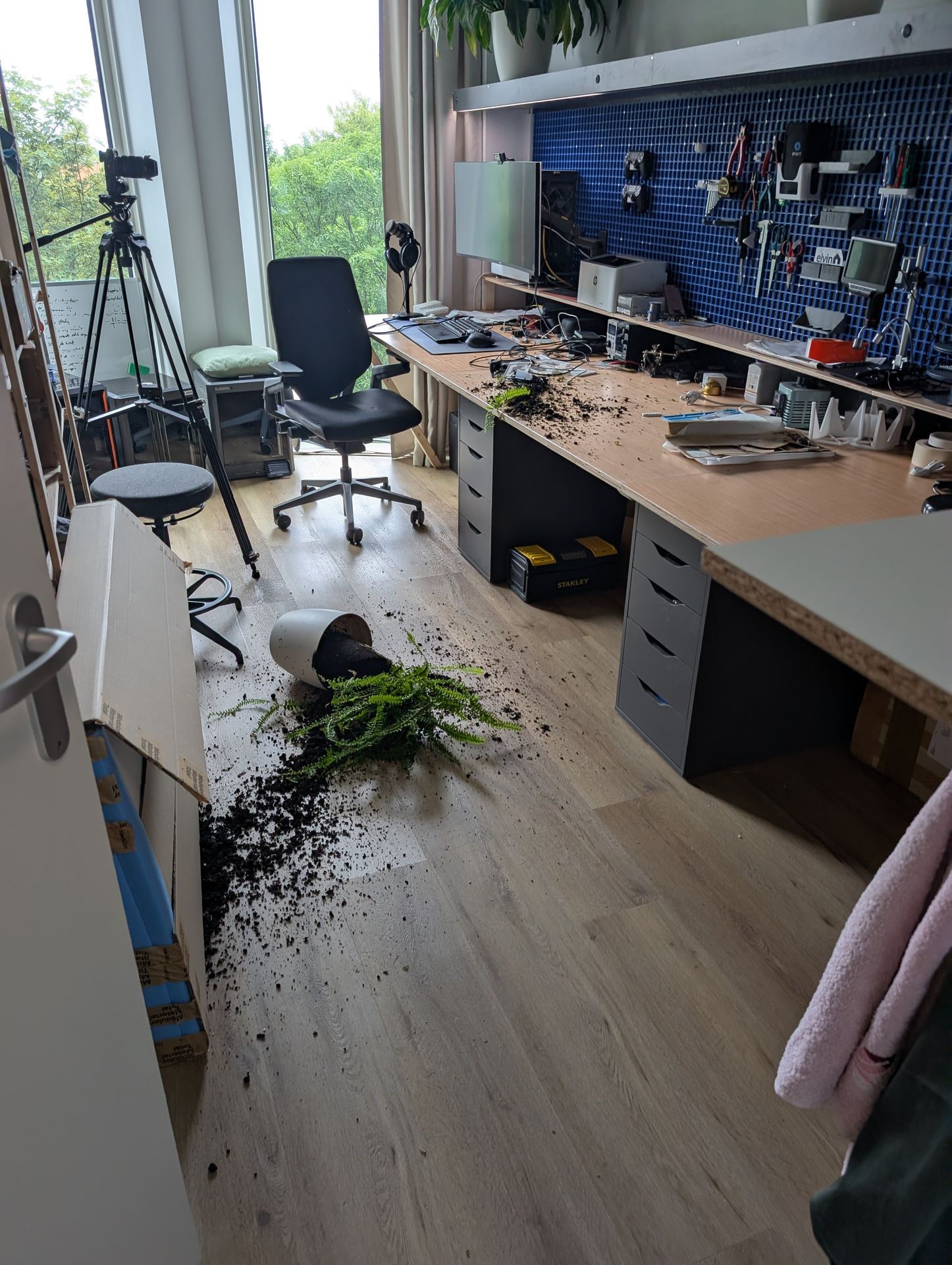
And while it makes a great place to put plants, remember: nowhere is safe from a cat.
ESPHome config
Here's how I got the firmware working on my PCB. This is definitely an example of a custom project tailored to my exact needs, but if you're interested in replicating it, definitely drop me a mail and I'll be happy to share the KiCad files with you too.
One interesting little bug I found in my setup was that trying to run the PWM lights and the RMT addressable LED strip at the same time resulted in the signal for the addressable strip going haywire, resulting in flashing lights. While the power supply can handle it, I never really intended to run both the white and RGB lights at the same time anyway, so there's some extra logic in here to make sure that only one of them can be on at a time.
esphome:
  name: light-shelf
  friendly_name: Study Shelf Light
  on_boot:
    then:
      - light.control:
          id: light1
          state: off
          color_mode: COLD_WARM_WHITE
          brightness: 60%
          color_temperature: 4400 K
      - light.control:
          id: light2
          state: off
          color_mode: COLD_WARM_WHITE
          brightness: 80%
          color_temperature: 4400 K
      - light.control:
          id: light3
          state: off
          color_mode: COLD_WARM_WHITE
          brightness: 80%
          color_temperature: 4400 K

esp32:
  variant: esp32c6
  framework:
    type: esp-idf


api:
  encryption:
    key: !secret encryption_key

ota:
  - platform: esphome

wifi:

esp32_improv:
  authorizer: none
  identify_duration: 30s

network:
  enable_ipv6: true

button:
  - platform: restart
    name: Restart
  - platform: safe_mode
    name: Restart (Safe Mode)

binary_sensor:
  - platform: gpio
    name: Button 1
    id: button1
    pin:
      number: GPIO19
      mode:
        input: true
        pulldown: true
    icon: mdi:light-switch
    disabled_by_default: true
    filters:
      - delayed_on: 10ms
    on_press:
      then:
        - light.toggle: light1
  - platform: gpio
    name: Button 2
    id: button2
    pin:
      number: GPIO21
      mode:
        input: true
        pulldown: true
    icon: mdi:light-switch
    disabled_by_default: true
    filters:
      - delayed_on: 10ms
    on_press:
      then:
        - light.toggle: light2
  - platform: gpio
    name: Button 3
    id: button3
    pin:
      number: GPIO22
      mode:
        input: true
        pulldown: true
    icon: mdi:light-switch
    disabled_by_default: true
    filters:
      - delayed_on: 10ms
    on_press:
      then:
        - light.toggle: light3
  - platform: status
    id: system_status

sensor:
  - platform: uptime
    name: Uptime
    id: uptime_sensor
  - platform: wifi_signal
    name: Signal Strength
    id: wifi_sensor

power_supply:
  - id: rgb_power
    pin: GPIO14
    enable_time: 0s
    keep_on_time: 0s

output:
  - platform: ledc
    id: led1
    frequency: 9765Hz
    pin:
      number: GPIO2
  - platform: ledc
    id: led2
    frequency: 9765Hz
    pin:
      number: GPIO3
  - platform: ledc
    id: led3
    frequency: 9765Hz
    pin:
      number: GPIO0
  - platform: ledc
    id: led4
    frequency: 9765Hz
    pin:
      number: GPIO1
  - platform: ledc
    id: led5
    frequency: 9765Hz
    pin:
      number: GPIO7
  - platform: ledc
    id: led6
    frequency: 9765Hz
    pin:
      number: GPIO6

light:
  - platform: cwww
    id: light1
    name: Left
    cold_white: led5
    warm_white: led6
    cold_white_color_temperature: 6500 K
    warm_white_color_temperature: 2400 K
    default_transition_length: 0.5s
    on_turn_on:
      - light.turn_off: rgb_light
  - platform: cwww
    id: light2
    name: Center
    cold_white: led4
    warm_white: led3
    cold_white_color_temperature: 6500 K
    warm_white_color_temperature: 2400 K
    default_transition_length: 0.5s
    on_turn_on:
      - light.turn_off: rgb_light
  - platform: cwww
    id: light3
    name: Right
    cold_white: led2
    warm_white: led1
    cold_white_color_temperature: 6500 K
    warm_white_color_temperature: 2400 K
    default_transition_length: 0.5s
    on_turn_on:
      - light.turn_off: rgb_light
  - platform: esp32_rmt_led_strip
    name: RGB
    id: rgb_light
    rgb_order: RGB
    pin:
      number: GPIO18
    num_leds: 72
    chipset: ws2811
    power_supply: rgb_power
    on_turn_on:
      - light.turn_off: light1
      - light.turn_off: light2
      - light.turn_off: light3
    effects:
      - addressable_rainbow:
      - addressable_color_wipe:
      - addressable_random_twinkle:
  - platform: status_led
    name: Status Ring
    disabled_by_default: true
    pin:
      inverted: true
      number: GPIO20
I use affiliate links for products that I use in my blog posts. The products themselves are chosen based on their merit and quality, and I buy them with my own money. If you get inspired by what I show, I'd appreciate you ordering via them so I get a small kickback, with no extra cost to you. Thanks for reading!