
Custom lighting PCB design frees you from many things - space constraints, creative limitations, all your free time and a large chunk of change. I wanted to do my grandmother's old incandescent floor lamp justice, creating new smart ESP32-powered LED lighting to replace the old light bulbs. Some assembly required.
Let's go into how I designed the PCBs using KiCad, and how I used PCBWay to get it all to my front door. This video isn't sponsored by them, but they did give me these boards for free.
Check out part 1 here with a video on the teardown of the lamp!
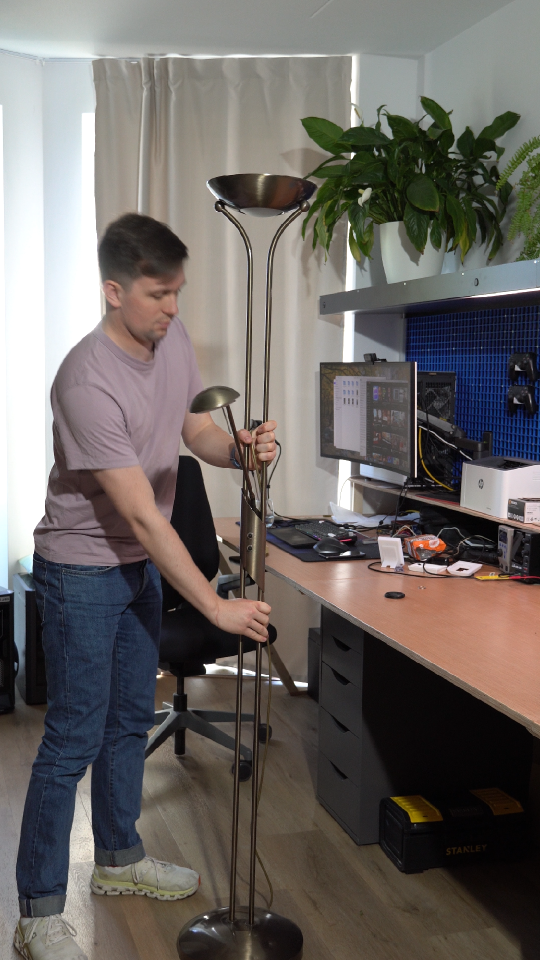
Here's what we're working with. This lamp was in my grandmother's house for as long as I can remember, and I did find a label inside that puts the manufacturer date in 2002. It's still perfectly functional, but while many in my grandmother's generation may have an "if it ain't broke, don't fix it" mentality, she went all in on LED. Now that she's upgraded away from this power-sucking incandescent model, I wanted to keep this one going by giving it an LED makeover of its own.
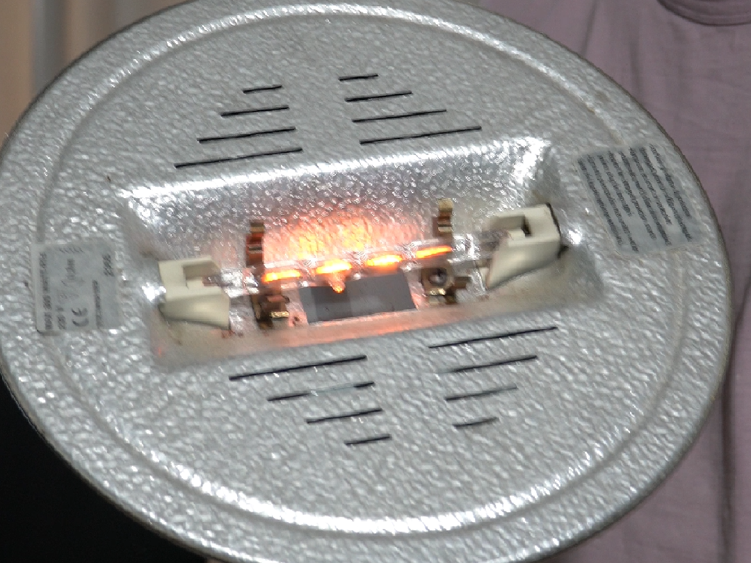
This long bulb is an absolute pain to find a replacement for. It gets super hot, so it's held in with a set of ceramic holders and surrounded by this large silver heat shield. There's a square opening in the bottom of it to allow some light to shine through the bottom of the fixture.
Disassembly
We won't be needing any of this, so let's remove it all:
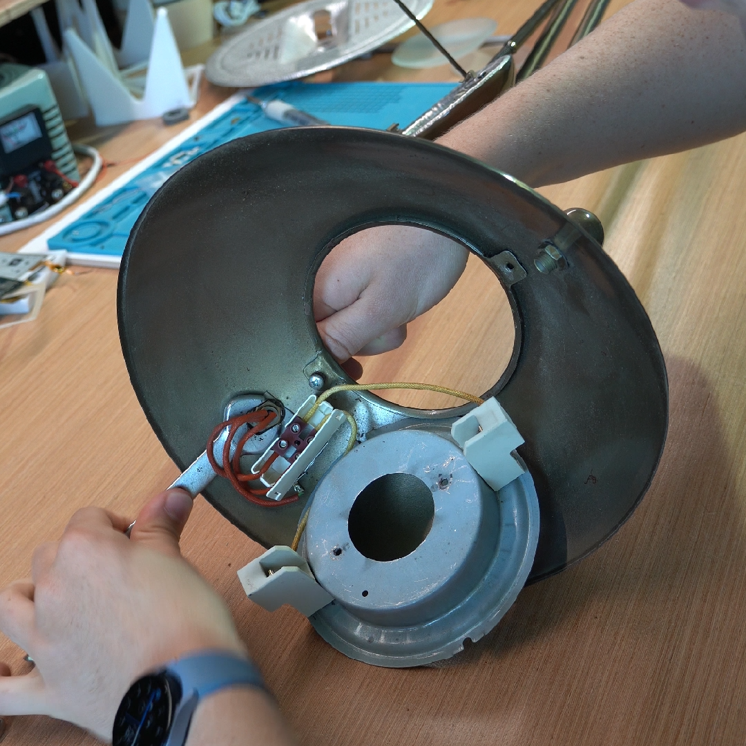 With the heat shield removed I could start to formulate my plan. I set the frosted glass piece that sits in the bottom aside, and we can see the ceramic holders are affixed to this metal piece. From here I started to make my plan; with the ceramic holders removed, there's two screw points on the top of the metal piece where I could place a PCB holding LEDs.
The PCB Plan
This is a project that I had on my list for a while now, and when PCBWay reached out asking if I wanted some free boards in exchange for a mention on the blog, it was definitely a win win.
First of all, let's lay out how the lamp worked originally. The main bulb is powered off 230V mains voltage, and the reading light is 12V. In the base of the light is a power supply board, and the potentiometers behind the knobs send a value back to the power supply to adjust the amount of power flowing to each light. So you could say that the "brain" of the lamp is in the base, albeit a very simple one.
I want to make this lamp smart, sticking an ESP32 in it and running ESPHome. While I could follow the same idea and design something to go in the base, this has a few key disadvantages:
- I want it to connect to WiFi, and putting it in the metal base would make the signal strength almost non-existent.
- I've got quite a few more wires to run for the new lighting as I want to do RGB, and colour temperature. Running them from the knobs down to the base and back has a lot more wiring.
- The knobs are using simple potentiometers which is great when it's only manually controlled, but they have a "0" and "100" position. I want to also control this over Home Assistant, so I want to swap them out with rotary encoders that can rotate infinitely anyway.
I opted to place a standard 24V power supply in the base, and put the brain behind the knobs. I then came up with a solution for both the main and reading light. The power flows up to the ESP32 board, and then cleanly splits from there to each of the lights. No complicated wiring, and the ESP32 is much better placed for WiFi connectivity.
The brain
For me, these projects always come with a "secondary" objective. While building this lamp I was also working on the CTRL ONE, the smart ePaper room controller that I make (check it out here!) and I wanted to experiment with a different DC-DC converter design, as well as an ESP32 module that I haven't tried before. There are a dozen ways I could think of to make this out of off-the-shelf dev boards and buck converters, but the point of the exercise is to experiment and learn.
While the brain board is well-positioned within the lamp, it's still housed inside of a metal enclosure which is bad for signal. I wanted to use something with an external antenna, so I could route the antenna up and out of a hole in the enclosure.
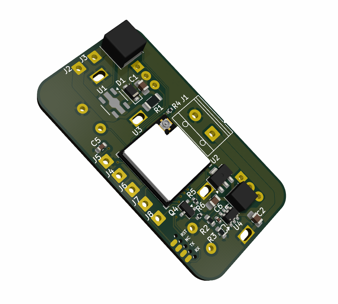
Here's the render from KiCad. On the back it contains the ESP32, along with power input, a 24V-3.3V DC-DC converter to power the microcontroller, and also the power circuitry to provide constant current to the reading light. The power circuitry for the main light is contained directly on that light's PCB, which I'll get to soon.
But the front is where we see how it comes together. After pulling out the calipers and measuring the distance between the old potentiometers, I made this board a drop-in replacement:
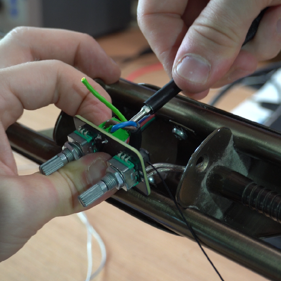
The rotary encoders are soldered directly to the PCB, feeding straight into the ESP32. It mounts perfectly behind the front fascia, and the knobs slot right on.
I had PCBWay do not only the PCB manufacturing, but also the assembly of the surface mount components. These ESP32 modules have all their pads on the bottom side, meaning it's not possible to visually inspect and make sure that everything is soldered correctly. PCBWay has x-ray machines to check all of this, and they'll be able to do a much better job than I ever could at home. Once I received the boards, the only thing I had to do was hand-solder the rotary encoders and screw terminals on; through-hole components that would have needed a human touch anyway.
The main light
This is where I went way overkill on my design. I spent ages researching for the best way to achieve this. The lamp is tall enough that the average person can't see the light produced directly, so looks weren't too important. I looked into large COB LEDs so that I'd only need to wire in one or two of them, but they're really not made for sale "direct to customer". Many good options I found were hard to obtain, and many more just didn't have the quality of light that I wanted. All the ceiling lamps and other lights in my home use the same LEDs that have a colour temperature of 2400K and 4000K, which allows you to mix them and get a temperature anywhere in this range. It's quite difficult to find LEDs under 3000K.
So I thought to myself... how hard can it be to make something of my own? I already designed a lot of my lighting using these Auxmer LED strips, and I really wanted to use the exact same LEDs so the lighting matched perfectly. The only issue is that they were on a flexible LED strip, while I wanted a PCB. Time to head to KiCad:
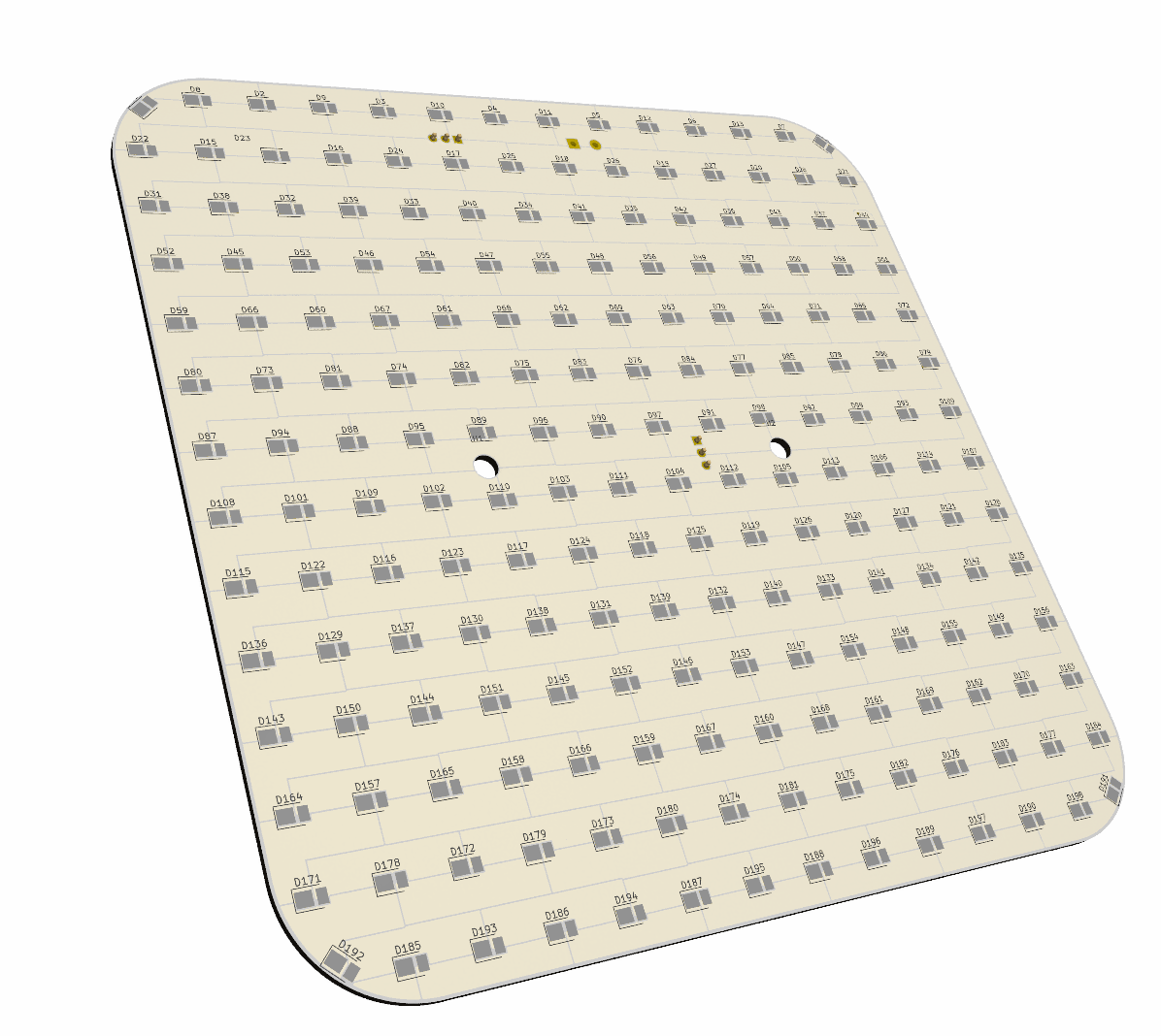
This was new to me and took a while to figure out. The board has an alternating array of cold white and warm white LEDs, which needed jumping through some mental hoops to get the pattern right. But the main concern was heat dissipation. There's 196 LEDs on this board in total! While each one doesn't produce that much heat, in total that's quite a lot to remove.
Initially I looked into getting an aluminium PCB made. PCBWay has great options for this, and if you're just looking to get a single-sided aluminium board made, it's pretty cost effective. However, because I have two sets of LEDs, there was just no way to route the traces without having them cross over each other at some point. The moment you try to move up to 2 or more layers for an aluminium PCB, it gets stupidly expensive and my rep basically told me there's no way they'd pay for that... fair enough.
After consultation with an LLM and doing some math, I realised that while the standard material of FR-4 PCBs is basically an insulator, the copper layer on top is very good at spreading heat. If I spaced out the LEDs enough and maximised the amount of copper connecting each one, the traces connecting each LED will not only be conductors of electricity, but act as heat spreaders also.
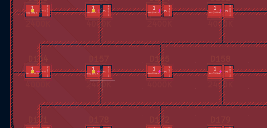
Zooming in on KiCad, you can see the arrangement. I did it by hand so it's not mathematically perfect, but each alternating LED is connected in series to each other through a large copper pour, allowing the heat to move too.
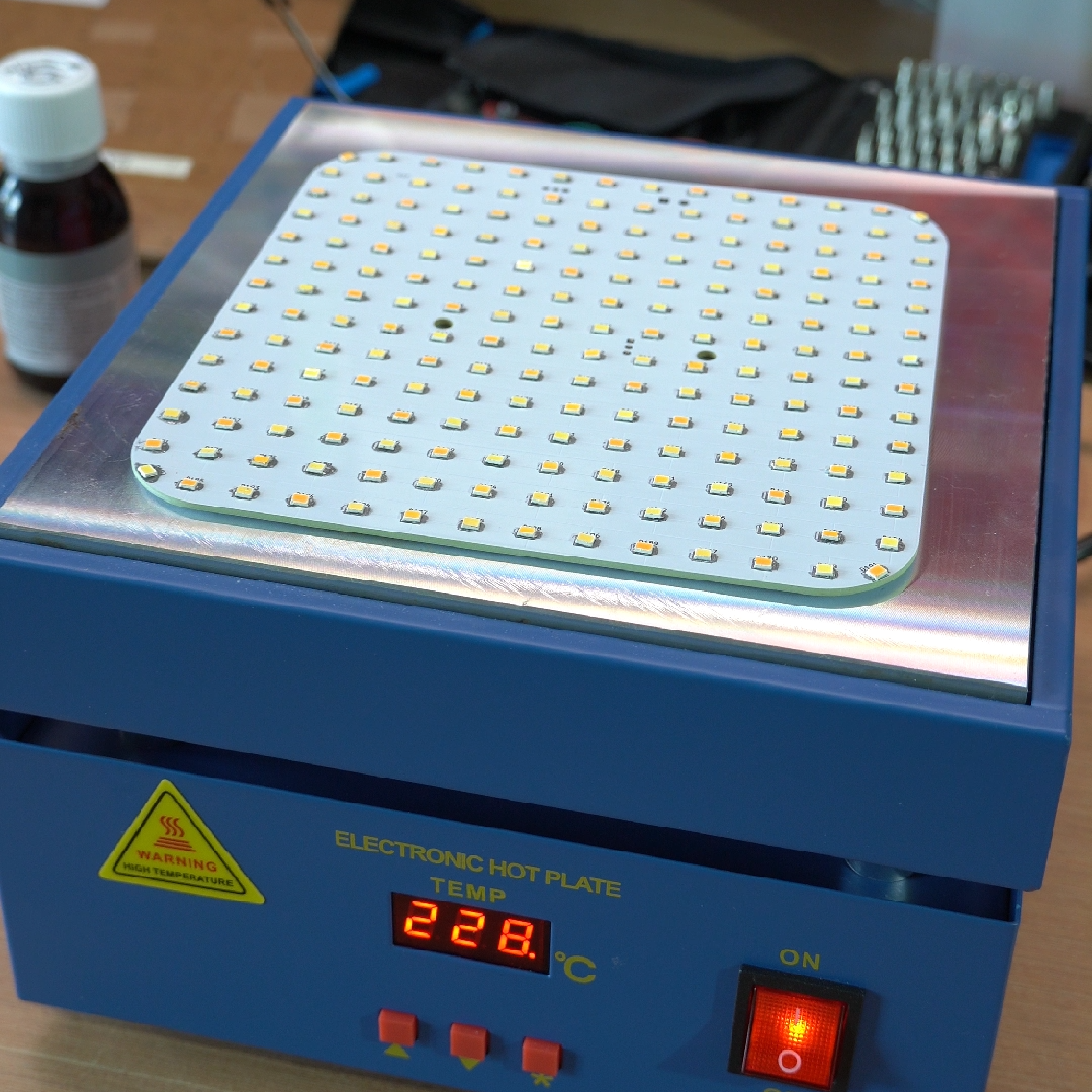
That's how I ended up with this huge 16cmx16cm board. After spending hours with a hot air rework station removing each LED from the strip one by one, then laying them out on the new board, a quick session on the hot plate soldered every one of them into place. Could I have done this a faster way? Sure. But already had those LED strips, so I was just trying to use up what I already had.
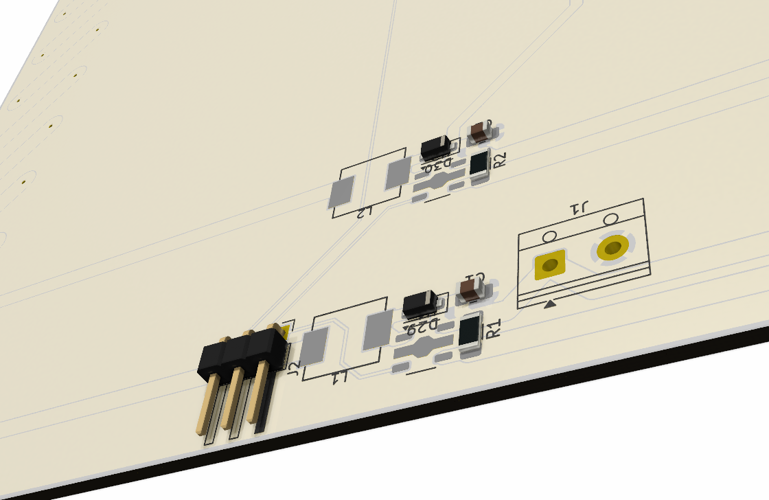
The flipside of the board had some components to go on too. This is where I tucked the 2 constant current LED drivers for each of the LED channels. I was again worried about heat dissipation in the enclosure around the knobs, and this side of the board has more than enough copper to keep it cool. Additionally, it includes an extra header to pass through a little bit of extra bling:
Bonus: ALL THE RGB
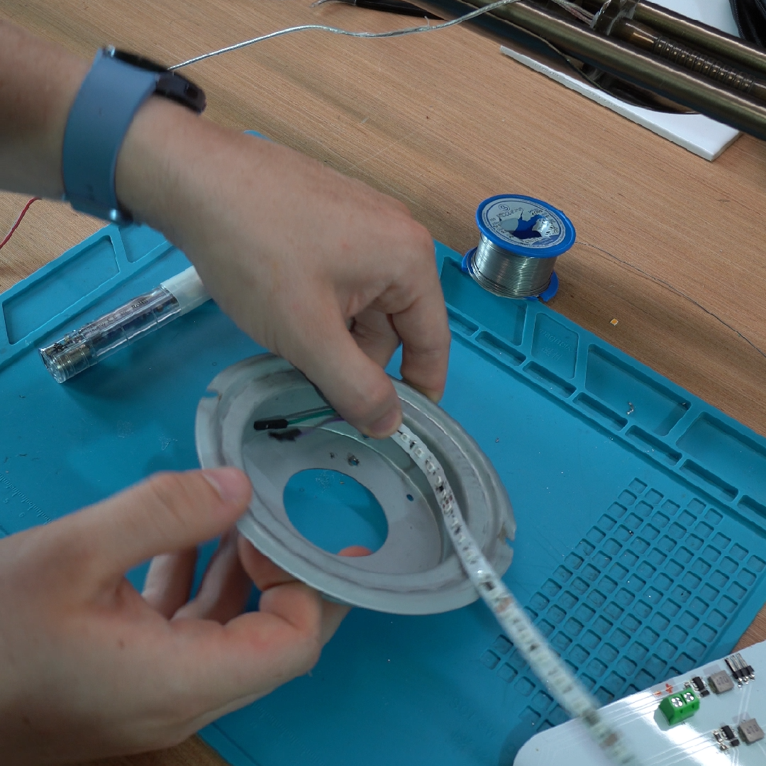
Since I'm going all in on smart lighting, why not go a little bit extra? This strip of addressable RGB lights form a ring, allowing to show cool colors and effects through the frosted glass on the bottom of the main light. It then connects into the lighting PCB, which provides 24V power and wires through the data line coming in from the ESP32 behind the controls.
This solves the issue with the new main light PCB where it doesn't shine light downwards through the frosted glass piece like the original lamp. It's controlled independently, and I also wrote a script that makes it mimic the colour of the lights above when it's not being used for notifications. It's mainly just a party trick.
The simplest part: the reading light
After spending all this time on designing two customs PCBs just for a floor lamp, I decided to leave it to someone else for the reading lamp. I bought this aluminium LED ring off AliExpress, wired it up and screwed it on down. Super simple.
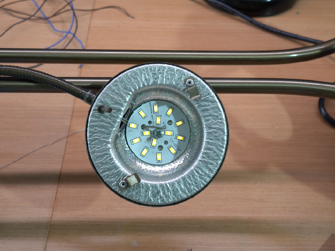
While the quality of the light is nothing to write home about, I was pleasantly surprised by how bright it gets, and how perfectly it fit into the lamp! It looks almost factory.
The power supply
While I'm happy to mess around designing my own little smart lighting PCBs, one thing I don't mess around with is power supplies. Unless I'm designing and rigorously testing one for general sale, it's best to leave it to someone else to do the hard work for you.
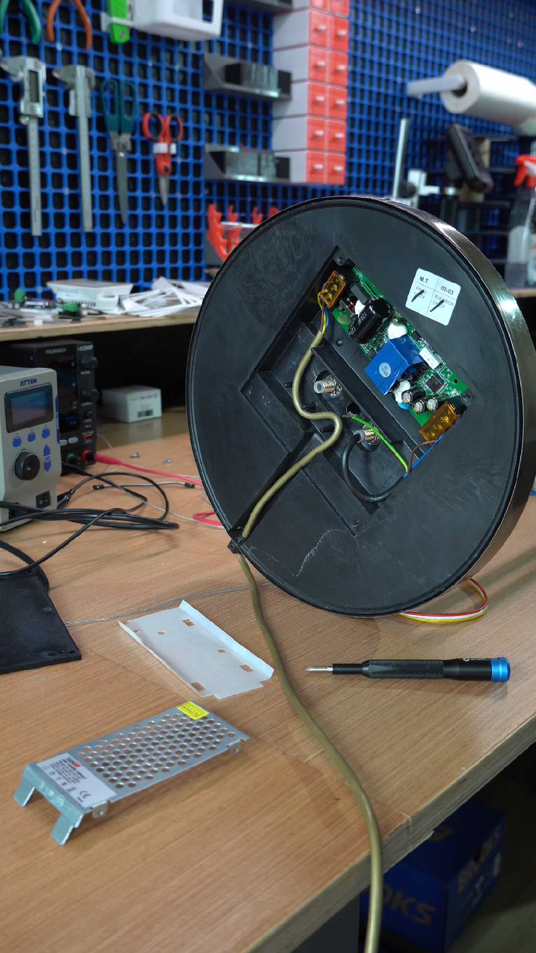
I picked up this SANPU 24V 100W unit off AliExpress, after checking the dimensions to see if it would fit in the base of the unit where the old power supply went. In the end it was a couple mm too tall with the casing on, but no worries - who needs that fancy protective casing anyway? I love getting 400V straight to the body.
Obligatory /s here. Don't remove the casing of a power supply unless you know what you're doing. In this case the base of the lamp itself is the casing, or at least that's how it was with the original supply. Once the panel is screwed in place, it should be just as safe as it was before. I was again worried about heat, so this power supply is severely over-specced - I measured 30-40W power draw with all lights on full, so this is running nowhere near its limits.
Putting it all together
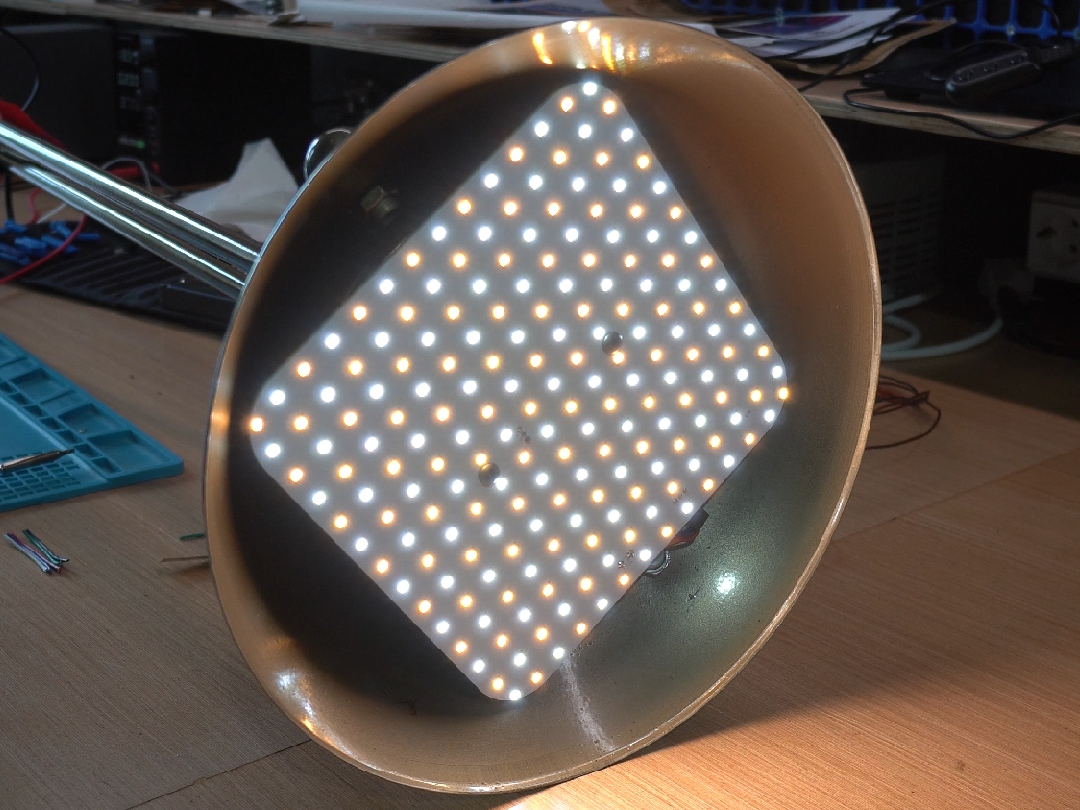
Here's what the main lamp looks like! I tested each LED individually before firing up the board, but once I applied power, every LED came to life. You can see the alternating matrix of cold white and warm white LEDs. In my living room, here's what it looks like:
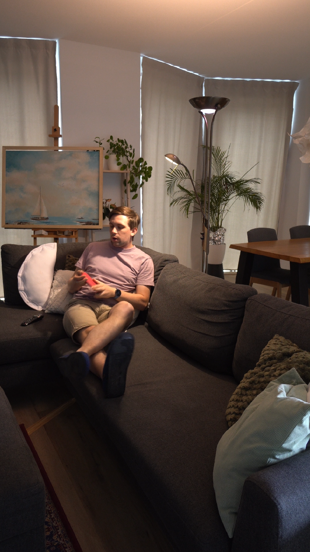
My biggest concern was that it wouldn't be bright enough, as while the strip the LEDs came off of is a bright strip, each individual LED only lets off a bit of light. I'm pleased to report that through the very scientific method of throwing an absolute f-ton of LEDs at the problem, it competes with my ceiling lights when turned up to 100%.
My experience
This was my first experience with PCBWay and I've gotta say: their customer service is excellent. I got one board assembled by them, and one board that I had to assemble myself. Both arrived in perfect condition with no faults and a clean silkscreen. It really is a case of "no news is good news" - I got exactly what I ordered in good time, and it worked.
I've often used PCB assembly services that require you to specify the exact components out of their catalogue to save a buck, and it was super nice to just tell them "hey, I need a 10K resistor here" and have them figure out which exact component to put down. I made a mistake on my BOM list and their engineers got back to me in no time to politely ask me what I was trying to achieve. I just emailed the fixed spreadsheet and everything continued smoothly.
In the end they were confident enough to give me these boards for free with no editorial oversight, and I've got nothing but praise for the quality of what I received. I'll definitely be using them for projects where time is of the essence and I need to be sure it works first try, because you get what you pay for.
But what can I say, I'm a cheapskate. I'm happy to sacrifice a little bit of time to save a little bit of money, and I often fall into the trap of forgetting what my own time is worth. And I've not learned any lessons here, so I'll keep using cheaper options to manufacture the CTRL ONE. Don't worry, every unit is tested thoroughly before it reaches you; I pay the price for bad boards ;)
Make it for yourself
Of course I built this for my specific lamp but if you want to take on a project like this as well, feel free to use my design as a base! I'm not saying it's perfect, but it definitely does the job.
I've uploaded the KiCad projects below, which includes all details on the components that I'm using. Enjoy.
Setting up ESPHome
For setting up your ESP32, here's the ESPHome config I used:
esphome:
  name: floor-lamp
  friendly_name: Floor Lamp
  on_boot:
    then:
      - light.control:
          id: main_light
          state: off
          color_mode: COLD_WARM_WHITE
          brightness: 80%
          color_temperature: 3000 K
      - light.control:
          id: reading_light
          state: off
          brightness: 80%

esp32:
  variant: esp32c6

api:

ota:
  - platform: esphome

wifi:
  ssid: !secret wifi_ssid
  password: !secret wifi_password

network:
  enable_ipv6: true

button:
  - platform: restart
    name: Restart
  - platform: safe_mode
    name: Restart (Safe Mode)

sensor:
  - platform: uptime
    name: Uptime
    id: uptime_sensor
  - platform: wifi_signal
    name: Signal Strength
    id: wifi_sensor
  - platform: rotary_encoder
    id: encoder_sw1
    pin_a:
      number: GPIO4
      mode:
        input: true
        pullup: true
    pin_b:
      number: GPIO3
      mode:
        input: true
        pullup: true
    on_clockwise:
      then:
        - if:
            condition:
              binary_sensor.is_on: encoder_sw1_press
            then:
              - script.execute:
                  id: adjust_color_temp
                  multiplier: 1.03
            else:
              - light.dim_relative:
                  id: main_light
                  relative_brightness: 5%
                  transition_length: 200ms
    on_anticlockwise:
      then:
        - if:
            condition:
              binary_sensor.is_on: encoder_sw1_press
            then:
              - script.execute:
                  id: adjust_color_temp
                  multiplier: 0.97
            else:
              - light.dim_relative:
                  id: main_light
                  relative_brightness: -5%
                  transition_length: 200ms
                  brightness_limits:
                    min_brightness: 20%
  - platform: rotary_encoder
    id: encoder_sw2
    pin_a:
      number: GPIO22
      mode:
        input: true
        pullup: true
    pin_b:
      number: GPIO23
      mode:
        input: true
        pullup: true
    on_clockwise:
      then:
        - if:
            condition:
              binary_sensor.is_on: encoder_sw2_press
            then:
              - light.dim_relative:
                  id: rgb_light
                  relative_brightness: 5%
                  transition_length: 200ms
            else:
              - light.dim_relative:
                  id: reading_light
                  relative_brightness: 5%
                  transition_length: 200ms
    on_anticlockwise:
      then:
        - if:
            condition:
              binary_sensor.is_on: encoder_sw2_press
            then:
              - light.dim_relative:
                  id: rgb_light
                  relative_brightness: -5%
                  transition_length: 200ms
                  brightness_limits:
                    min_brightness: 5%
            else:
              - light.dim_relative:
                  id: reading_light
                  relative_brightness: -5%
                  transition_length: 200ms
                  brightness_limits:
                    min_brightness: 20%

binary_sensor:
  - platform: gpio
    id: encoder_sw1_press
    pin:
      number: GPIO5
      inverted: true
      mode:
        input: true
        pullup: true
    on_click:
      then:
        - light.toggle: main_light

  - platform: gpio
    id: encoder_sw2_press
    pin:
      number: GPIO21
      inverted: true
      mode:
        input: true
        pullup: true
    on_click:
      then:
        - light.toggle: reading_light

script:
  - id: adjust_color_temp
    parameters:
      multiplier: float
    then:
      - lambda: |-
          auto vals = id(main_light).remote_values;
          if (!vals.is_on()) return;
          float ct = vals.get_color_temperature_kelvin();
          ct *= multiplier;
          if (ct > 6500.0) ct = 6500.0;
          if (ct < 2400.0) ct = 2400.0;
          auto call = id(main_light).turn_on();
          call.set_color_temperature(ct);
          call.set_brightness(vals.get_brightness());
          call.set_transition_length(200);
          call.perform();

output:
  - platform: ledc
    id: main_led_ww
    frequency: 1220Hz
    pin:
      number: GPIO14
  - platform: ledc
    id: main_led_cw
    frequency: 1220Hz
    pin:
      number: GPIO15
  - platform: ledc
    id: reading_led
    frequency: 1220Hz
    pin:
      number: GPIO2

light:
  - platform: cwww
    id: main_light
    name: Main Light
    cold_white: main_led_cw
    warm_white: main_led_ww
    cold_white_color_temperature: 6500 K
    warm_white_color_temperature: 2400 K
    default_transition_length: 0.5s
    on_state:
      then:
        # Calculates an equivalent color to the current color temperature of the main light
        # Then turns on the RGB LEDs to be that color to match
        - lambda: |-
            auto vals = id(main_light).remote_values;
            if (!vals.is_on()) {
              id(rgb_light).turn_off().perform();
            } else {
              float kelvin = vals.get_color_temperature_kelvin();
              if (kelvin < 1000.0f) kelvin = 1000.0f;
              if (kelvin > 40000.0f) kelvin = 40000.0f;
              float k = kelvin / 100.0f;
              float r, g, b;
              if (k <= 66.0f) {
                r = 1.0f;
              } else {
                r = (329.698727446f * std::pow(k - 60.0f, -0.1332047592f)) / 255.0f;
              }
              if (k <= 66.0f) {
                g = (99.4708025861f * std::log(k) - 161.1195681661f) / 255.0f;
              } else {
                g = (288.1221695283f * std::pow(k - 60.0f, -0.0755148492f)) / 255.0f;
              }
              if (k >= 66.0f) {
                b = 1.0f;
              } else if (k <= 19.0f) {
                b = 0.0f;
              } else {
                b = (138.5177312231f * std::log(k - 10.0f) - 305.0447927307f) / 255.0f;
              }
              if (r < 0.0f) r = 0.0f; if (r > 1.0f) r = 1.0f;
              if (g < 0.0f) g = 0.0f; if (g > 1.0f) g = 1.0f;
              if (b < 0.0f) b = 0.0f; if (b > 1.0f) b = 1.0f;
              auto call = id(rgb_light).turn_on();
              call.set_rgb(r, g, b);
              call.set_brightness(vals.get_brightness());
              call.set_transition_length(id(main_light).get_default_transition_length());
              call.perform();
            }
  - platform: monochromatic
    id: reading_light
    name: Reading Light
    output: reading_led
  - platform: esp32_rmt_led_strip
    name: RGB
    id: rgb_light
    rgb_order: RGB
    pin:
      number: GPIO18
    num_leds: 5
    bit0_high: 350ns
    bit0_low: 900ns
    bit1_high: 700ns
    bit1_low: 600ns
    reset_low: 300us
    default_transition_length: 0.5s
    effects:
      - addressable_rainbow:
I use affiliate links for products that I use in my blog posts. The products themselves are chosen based on their merit and quality, and I buy them with my own money. If you get inspired by what I show, I'd appreciate you ordering via them so I get a small kickback, with no extra cost to you. Thanks for reading!