
Does Carlos drink enough water? To find out, I'm going to use ✨ technology ✨. Seeed Studio sent me their human presence detecting kit, with the XIAO ESP32-C6 and some Grove sensors. I decided to use it on my cat. I'm sure that's not what they intended, but that's their problem, not mine.
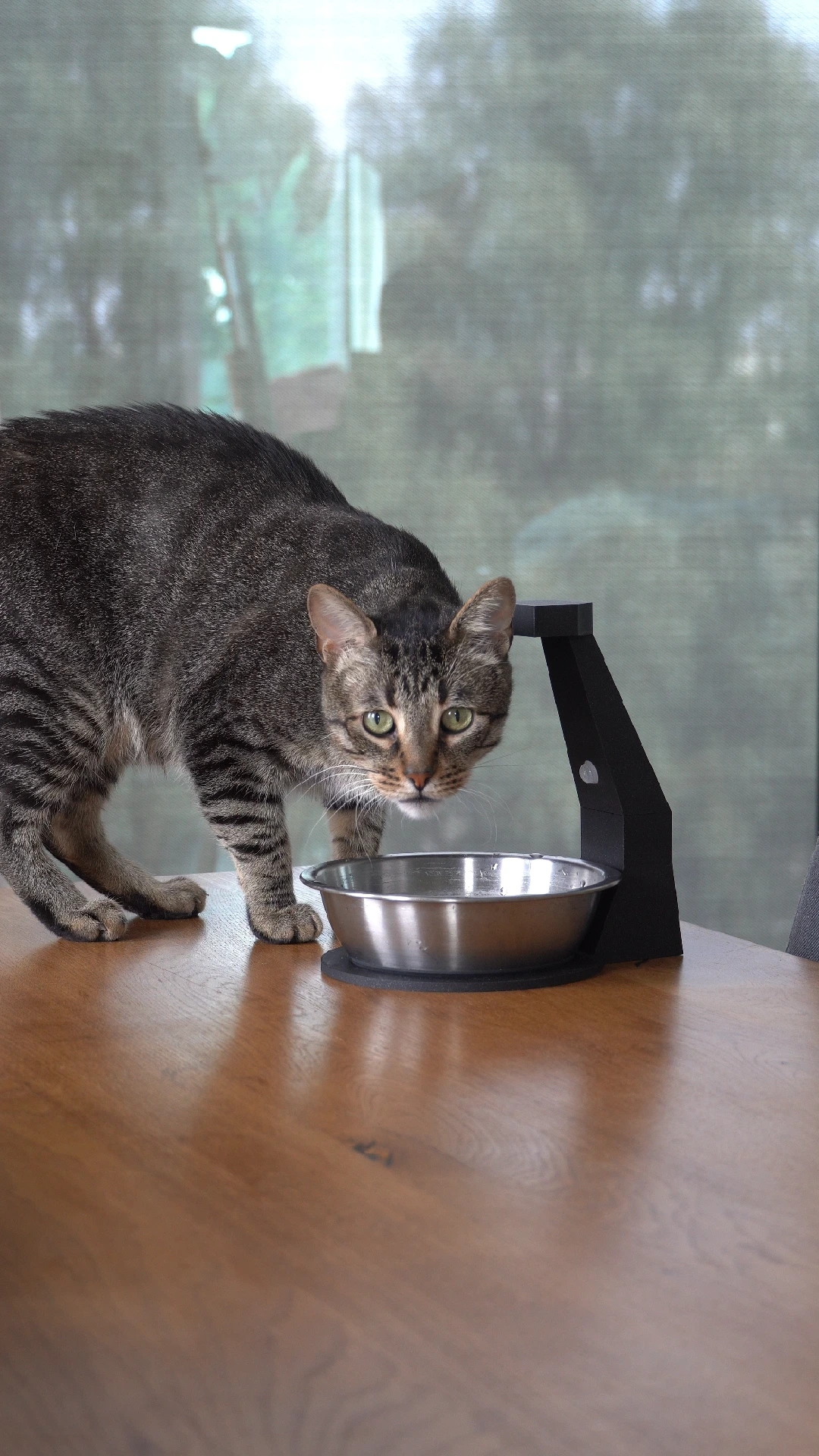
This is Carlos. He's a single son to two millennial parents who don't want to commit to a human child, and we got him as a rescue cat from Spain. During the most recent heatwave here in the Netherlands he spent most of it just lying in the 40 degree sun, and I think I've only ever seen him actually drink from his water bowl once.
I've grown up with cats and am very much of the mindset that you don't need to spend much to entertain a cat. The living room is a maze of cardboard boxes that he spends hours in, and his favourite toy is a few feathers on a stick. I'm not going to run out and spend money on some fancy filtered water fountain, but I do want to know if he's staying healthy.
Not long before, Seeed Studio reached out and asked if I wanted to take a look at their Human Detecting ESPHome DIY Kit. I responded with one question: Can it detect a cat?
Their answer basically was along the lines of "uh... no. It's a human presence detecting kit." But I didn't listen to them; after all, Carlos is my baby. They relented and sent over the kit anyway. Thanks guys.
While I got this for free, they don't have any say over what I say. They just want me to make something and write about my experience with it, so here you are.
My plan is simple: I want to know when Carlos drinks water, and it would be really cool to know how much. For this, we need a way to know when he approaches the bowl, and how much water is in it. We'll know if he actually drank, because the water level should be lower when he moves away again.
Starting with the electronics
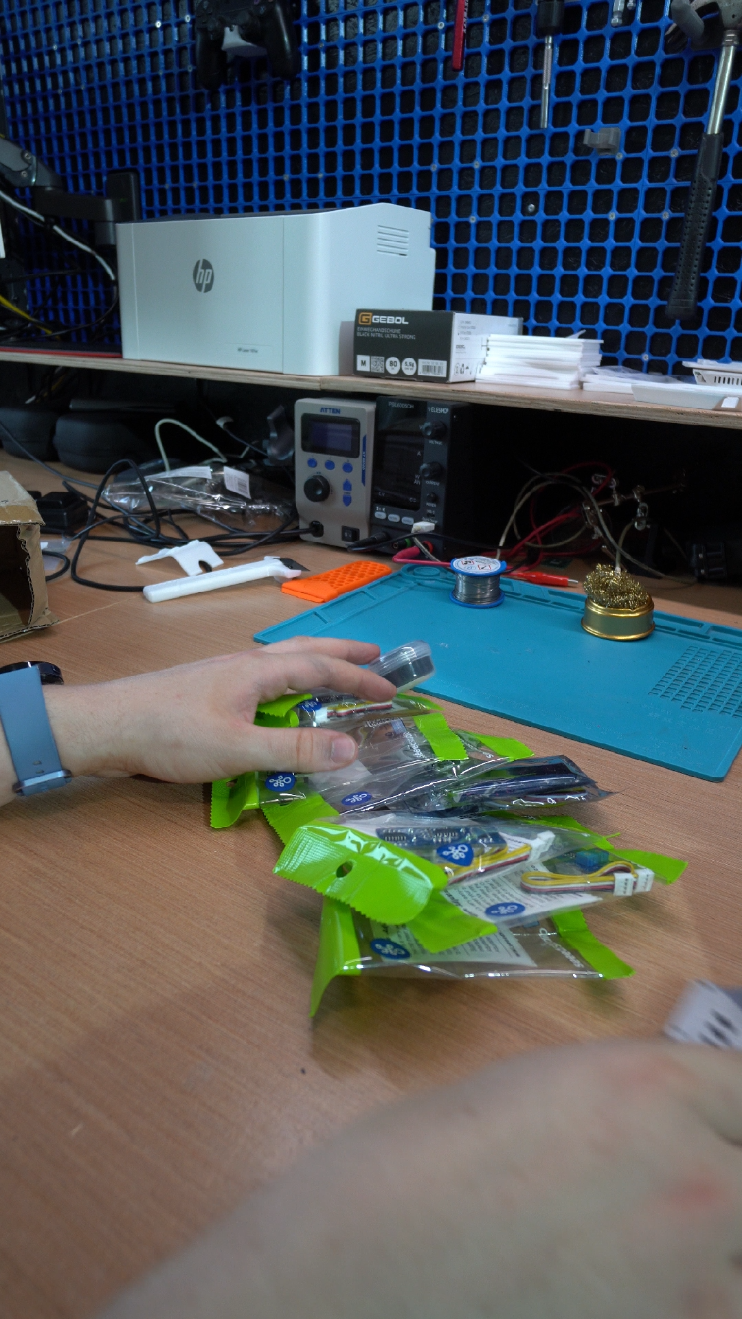
The care package arrived in short order, and I got two of each:
- XIAO ESP32-C6
- Grove Base for XIAO - connects the ESP32 to the sensor modules
- Grove Ultrasonic Distance Sensor
- Grove Adjustable PIR Motion Sensor
- 24GHz mmWave Human Static Presence Sensor
You'll notice in this list that I actually got two different sensors that could detect presence/motion. I thought I'd mention it anyway - while the 24GHz sensor is super cool and I've got some ideas for projects with it in the future, that one really is not designed for cats. It literally has "human" in the name. Plus, it doesn't work well when water moves nearby. So I'm going to be using the PIR Motion Sensor for this project.
The ultrasonic sensor needs to face downwards, towards the water. It will bounce sound waves off the surface and measure the distance, and with this we'll know the water level. The PIR motion sensor has an adjustable sensitivity so with some good positioning, I should be able to accurately detect Carlos' head approaching the water bowl without getting false positives from the surroundings.
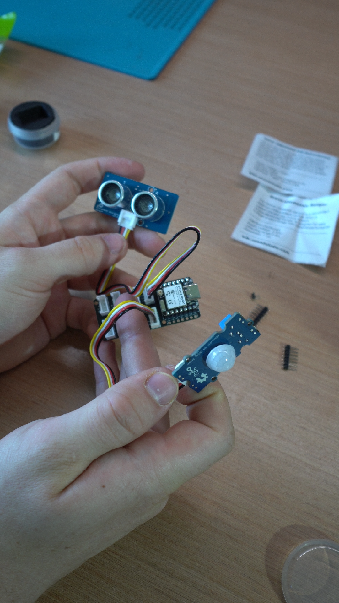
Everything just slots together like little LEGOs. I often tend to do things the hard way, making my own custom PCBs as it's tidy and pretty affordable to do these days. But for small one-off projects like this, it's been a huge time saver. Of course the final result is going to be a bit bulkier, but I can live with that. Before I go building anything though, it's time to do some testing to make sure this kit can do what I need it to do.
Getting firmware on the hardware
My favourite firmware for any project like this is ESPHome. It's super simple to write a quick configuration file, compile and flash a firmware, and then get the data all in Home Assistant. I can then use that to collect all the data so I can look back and see how much the water level changes, along with when he uses it. The PIR motion sensor is easy - it just sends a simple on/off signal when it detects something or not.
I thought the ultrasonic sensor was going to be a breeze too. ESPHome has an Ultrasonic Distance Sensor component, so this should be plug and play, right?
Wrong.
What ESPHome is expecting is to have two different pins. On one pin, the ESP32 sends a pulse to the device, which makes it send out a series of sound waves. On the second pin, a series of response pulses are sent back, and the ESP32 measures the time between the received pulses. It then computes the distance based on how long it took the sound to travel. Seeed Studio has done something pretty innovative with their sensor, however. Onboard the sensor is a tiny MCU that combines the two pins together. Now the ESP32 is expected to send a pulse, then immediately receive the response on the same pin. The rationale is simple: there's no way that a pulse and response can be sent at the exact same time, so this saves us one precious GPIO pin.
This however reveals an error on Seeed Studio's part. This kit is advertised as an "ESPHome DIY kit", but this method of combining the pins is not actually supported by the ESPHome ultrasonic component, meaning their sensor doesn't work out of the box.
I took the existing ultrasonic sensor component as a reference and made a new component that supports this sensor specifically, automatically switching the pin between an input and output at the right times to send and receive the pulses from the sensor. I made a pull request that is pending as of the time of writing, which you can find here: https://github.com/esphome/esphome/pull/17086
I definitely feel like I'm doing their job for them but I'm already an active contributor to the project as part of getting it ready for the CTRL ONE, my own product. It didn't take too long to fix, but it might take a few more months before it's added to a new release of ESPHome.
Battery power
This is the first project I've done using batteries to power an ESPHome device. My principle of anything home automation related is that it shouldn't use batteries as I'll always forget to replace them. Generally ESP32s are known to be a little on the power-hungry side, but I thought I could counteract this by just stuffing in enough batteries.
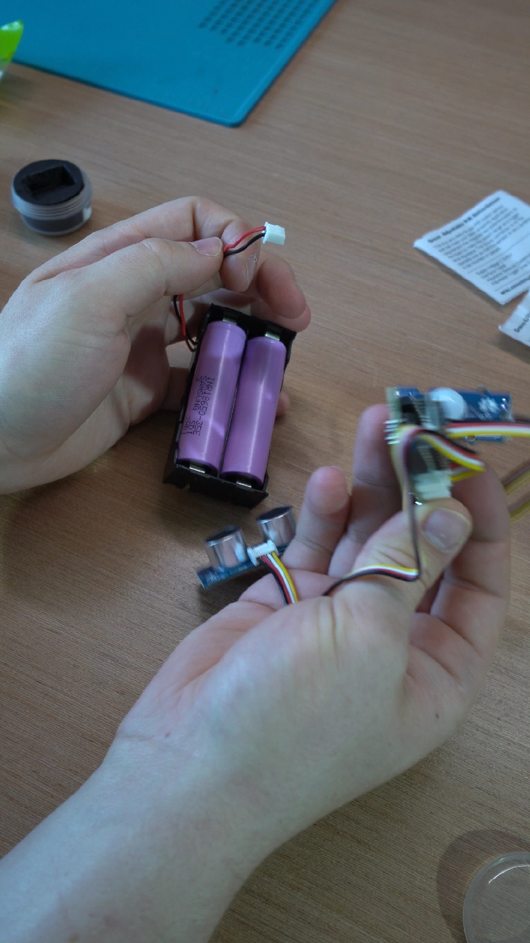
I have a large stash of 18650 cells lying around from an old e-bike battery I disassembled, so this was a no-brainer. By using two of them, I should have more than enough for it to last a long while, or at least that's the theory. I'm using a battery holder that I had lying around, and on the back I wired both of the cells to be in parallel.
What's super neat is that both the XIAO ESP32-C6 module and the Grove Base board have battery charge circuits on them. I did ask my Seeed Studio rep which one was the "right" one to use, and I just got back the answer "you choose". I went with the one on the Grove board. Included in the package was a little header that I needed to solder onto the board, while the ESP32-C6 requires you to solder wires directly to some exposed pads on the bottom. This means that if I need to remove the ESP32, everything stays nicely attached to the Grove board.
It works great! One thing that got me a little confused it that when it's plugged in through USB power, there are a couple LEDs that stay on so you know it's powered. When on battery power, they're not lit. I thought it wasn't working for a little while, before I noticed that data was actually being received in Home Assistant. Overall it makes sense - I don't want my precious battery being wasted on an LED I don't control. Good design.
Overall though, I knew WiFi is an absolute battery drain, so I've got another video and post coming soon where I investigate OpenThread on battery power! Stay tuned for that one.
3D modelling it all together
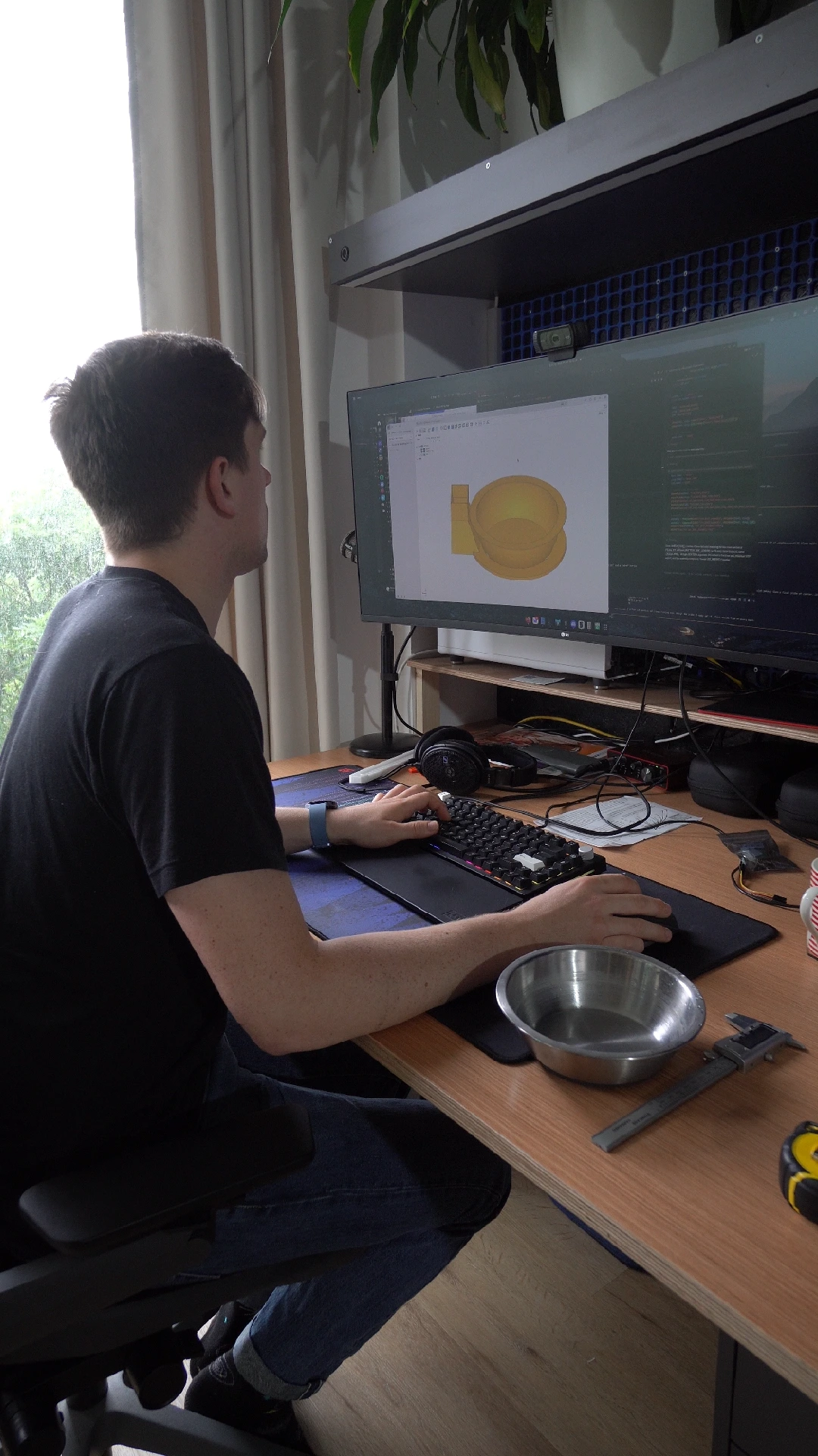
Here's the bowl in question. I picked this up for €2 second hand, and I'm pretty sure in its past life it was a dog food bowl. It's quite big for a cat, and while we do refill it regularly, it's nice to be able to fill it up more if we need to go away for a few days. First order of business was busting out the calipers and making a rough 3D model of the bowl itself.
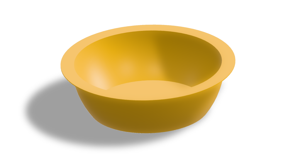
I make all my 3D models in Python, using build123d. I'm not claiming it's the best 3D modelling software out there, but it's free! And as I already knew how to write code, it's what came naturally to me as I was getting into 3D modelling. When I combine it with some AI tools, I can make simple models like this super quickly.
The structure of the device is made of two parts:
- A base that keeps the water bowl in place, and houses the battery,
- A "neck" that holds the rest of the electronics, points the motion sensor angled downwards and forwards, and the ultrasonic sensor at the top pointed downwards.
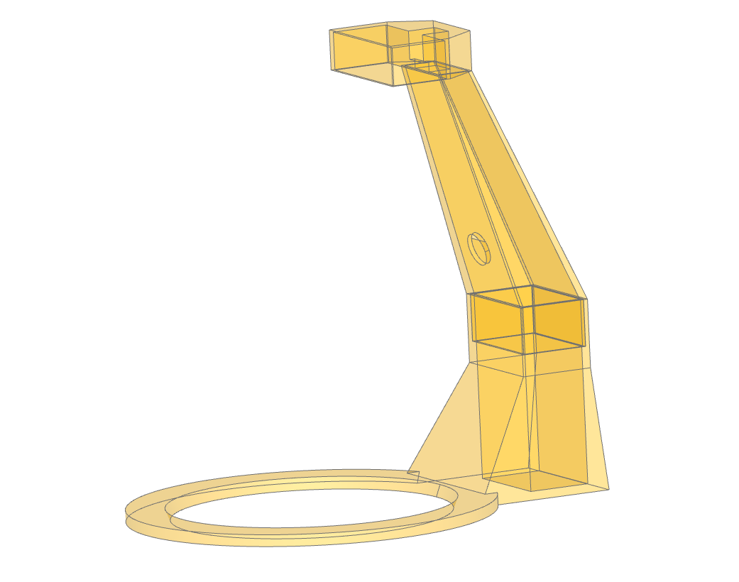
Here's what I came up with. I decided to lean into the angular design, and the top part nicely slides down and into the base that holds the battery box. There's a small hole in the neck where the PIR motion sensor pokes out of, and the natural shape of it angles it towards the bowl.
At the top, looking a bit like a street lamp, is a place to mount the ultrasonic sensor.
Bringing it into the real world
This entire design is made to be 3D printed, and you can find the 3MF, STEP and original Python files all over on Printables! It's designed for everything to friction fit together, so no glue or screws. Just get the Seeed Studio parts, print and play. Of course I've only tested with my parts so there may be some slightly different tolerance issues, but you've got the original model files to play with.
I chose some Prusament Galaxy Black PLA for this, just because it's the nicest looking filament that I had on hand. A neutral colour helps make this blend in a little to the background.
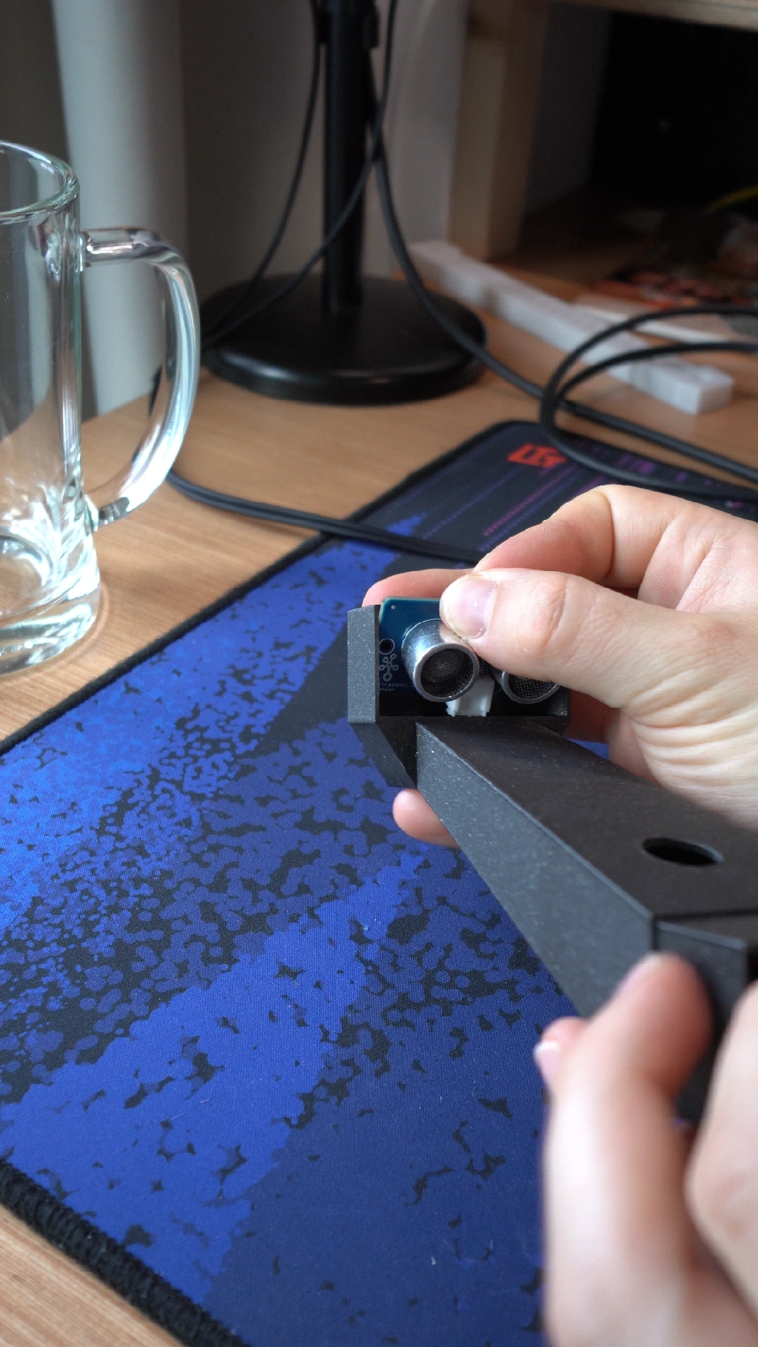
With the parts printed, I first feed the cable down the small gap into the neck, and the ultrasonic distance sensor gets pushed in. Next up, both the ultrasonic sensor and PIR sensor should be connected to the Grove board. Your choice on where you connect them, just make sure to take a picture so you know which GPIOs to configure in ESPHome later.
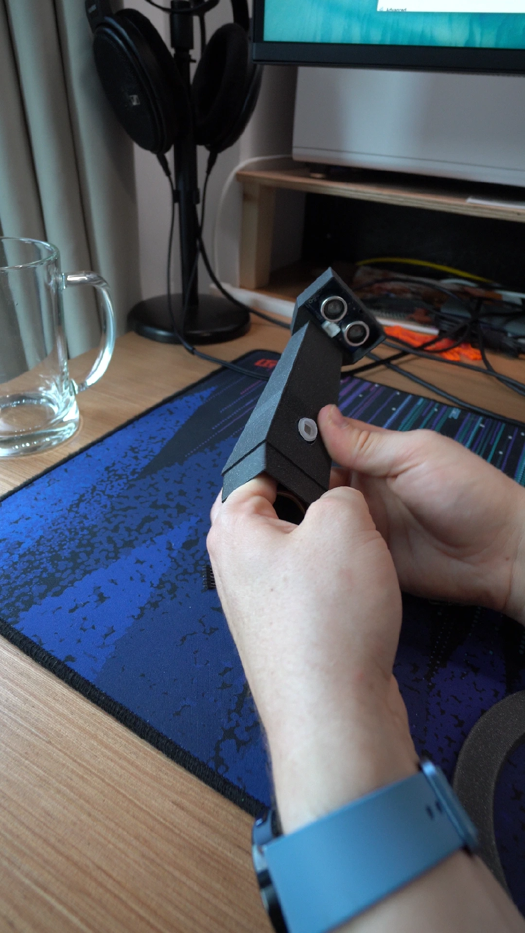
Before putting in the PIR sensor, you'll want to check the wiki and adjust the screw for the sensitivity. You want it to detect your hand waving from no more than 20cm away. I set the PIR hold time to the minimum - if I need it to stay as "motion detected" for longer, I'll extend it in software.
Here comes the tricky part, and the part I'm least proud of. When I said that everything friction fits together, I meant it! None of these parts have neat little mounting brackets or anything of the sort. It's designed to all be jammed into the neck of the device, and it should just fit. First make sure the cables are neatly routed to the sides, and position the PIR sensor in with the lens removed.
Once that's done, slowly move the ESP32 board into place directly behind the PIR sensor, wedging it into place. You want the USB port facing out the hole in the bottom, so you can power it up without batteries for testing and reprogram it if needs be.
This might take a few tries to get it right. You definitely want to make sure everything is tested and working before you start. If it's stuck, it's likely one of the wires got in the way. The PIR sensor should be rotated at a 30 degree angle or so - it doesn't need to be straight, as long as the actual sensor pokes out of the hole.
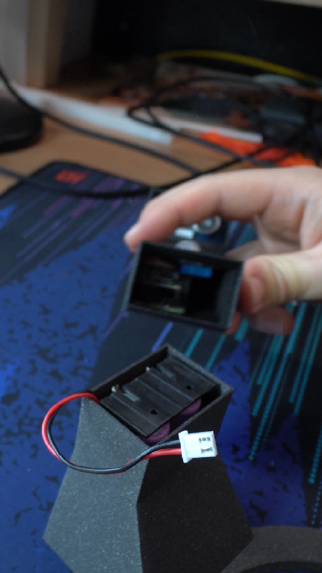
Lastly, the battery holder slides into the bottom of the case, and it's time to connect the two parts together! I'm using a little JST plug that fits over the little header that came with the Grove board, to make assembly easier.
Here's where I messed up. With everything installed, you can't see the markings on the board that tells you which side is positive and which is negative... and I accidentally connected the battery the wrong way around. The result was a sharp puff of smoke, and that was the end of my battery charge circuit! The magic smoke that powers the electronics had escaped. So make sure to write this down before you slide everything in.
This is exactly why I asked for two of everything, so I pulled out the second Grove board and was off to the races again. I really like how friendly Seeed Studio has made this XIAO + Grove kit, with everything slotting together. But in the end it's still a development kit, and there are some things that are just not idiot-proofed enough for idiots like me. The battery circuit not having any reverse polarity protection did surprise me, even though I was being mindful to not do it accidentally... until I did. Combine that with the fact the battery header did not come pre-soldered onto the board makes me feel like that the battery circuit was just a very nice afterthought. Still, I'm very glad to have it, as without it, I would have needed to add yet another board into an already confined space.
Slotting it all together
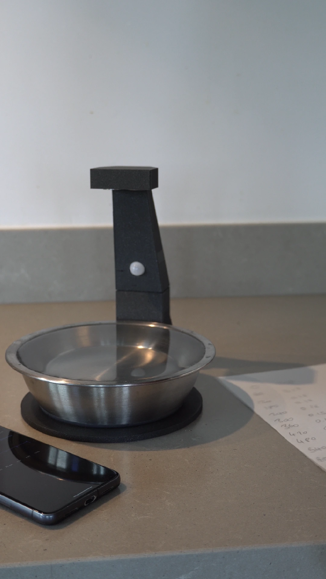
With the neck put down onto the base, we have the final result! The bowl sits nicely in its circular cradle, and the ultrasonic sensor is positioned at just the right point so it's able to get the water reading all the way to the bottom of the bowl. The last thing is to "calibrate" the ultrasonic sensor.
I had a 60ml cup, so I added one scoop of water at a time and recorded the distance reading from the sensor. This is where I hit a minor snag. The precision of the sensor is rated to +/- 1 centimetre. This means that the reading at this distance is just not very accurate, but I don't think that's a major issue. While I do have it outputting a water reading in millilitres, it's more just an indication of whether the bowl is nearly empty, or nearly full. Over the longer period, it'll do what I need it to do, which is tell if Carlos is actually drinking.
So how useful is this project in general? It was definitely fun to build, but the big question is what I'll do with the data when I've got it. It's not like I can just ask him to drink more water. But it's interesting to know when he does, and I've also got a Home Assistant notification set up to alert me if the bowl is running empty. The power of automation.
I'll definitely be using the XIAO ESP32-C6 modules from Seeed Studio more in the future. They're super small and have loads of features. I especially like the integrated battery circuit, boot/reset buttons and indicator LED. The ability to switch between the onboard antenna and an external one could come in handy too. As for the sensors; I think I'll keep making custom PCBs, and buying cheap sensors from AliExpress. I much prefer to design the board to fit the space rather than the other way around, and I don't feel I did a great job getting it all crammed into this device. I could definitely see myself slotting the XIAO ESP32 into my own board designs though.
Check out part 2 here where I take a deep dive into the world of ESPHome and OpenThread. You'll find the ESPHome configuration there!