
I design plenty of different PCBs for projects on this channel, and most of them involve a microcontroller, namely the ESP32. I love this mini boards as I can make the layout super small, saving money and space, but I need some way to flash the firmware to them. Enter, stage right, SOICBite. I love it, and thought I'd show it to you, in case you haven't heard of it.
If you're just looking for the link to it, here you go! https://github.com/SimonMerrett/SOICbite
It's a little "connector" that you add to the edge of your PCB. You then attach a programmer/debugger (basically just a UART serial device) via a clip that holds onto the edge of the board, like so:
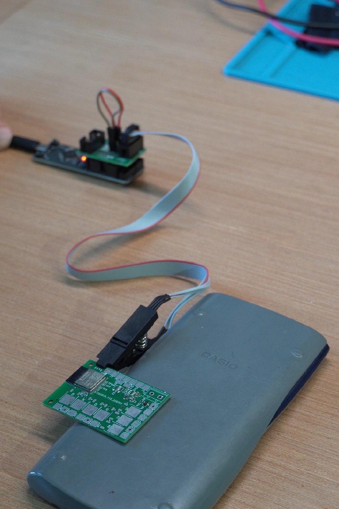
In the end it's just an SOIC-8 clip. This clip is designed for programming microcontrollers that use the SOIC-8 format, by clamping onto the microcontroller's pins directly before it's soldered onto the board. However these days microcontrollers come in much smaller packages, with many more pins, so there's just no practical way to flash firmware to them directly; instead, it's more common practise to solder them down to the PCB first, and then provide an outside interface via the PCB to connect to the chip.
For devices I sell such as the CTRL ONE, the answer is simple - since I need to include a USB port to power the device anyway, it might as well also expose the ESP32's programming interface. This is how I program them before shipping them out as well, and it's certainly the most robust. However, many of my projects involve embedding a PCB into the middle of a piece of furniture or appliance, where it's powered off a DC power supply and is not easily accessible. While I could put a USB port on them, that component is just an unnecessary extra expense while taking up board space that I could save instead.
While the component itself only costs a few cents, I generally have these boards assembled for me at the PCB manufacturer, and each individual component generally has a $3 loading fee, so using fewer different components saves up a lot.
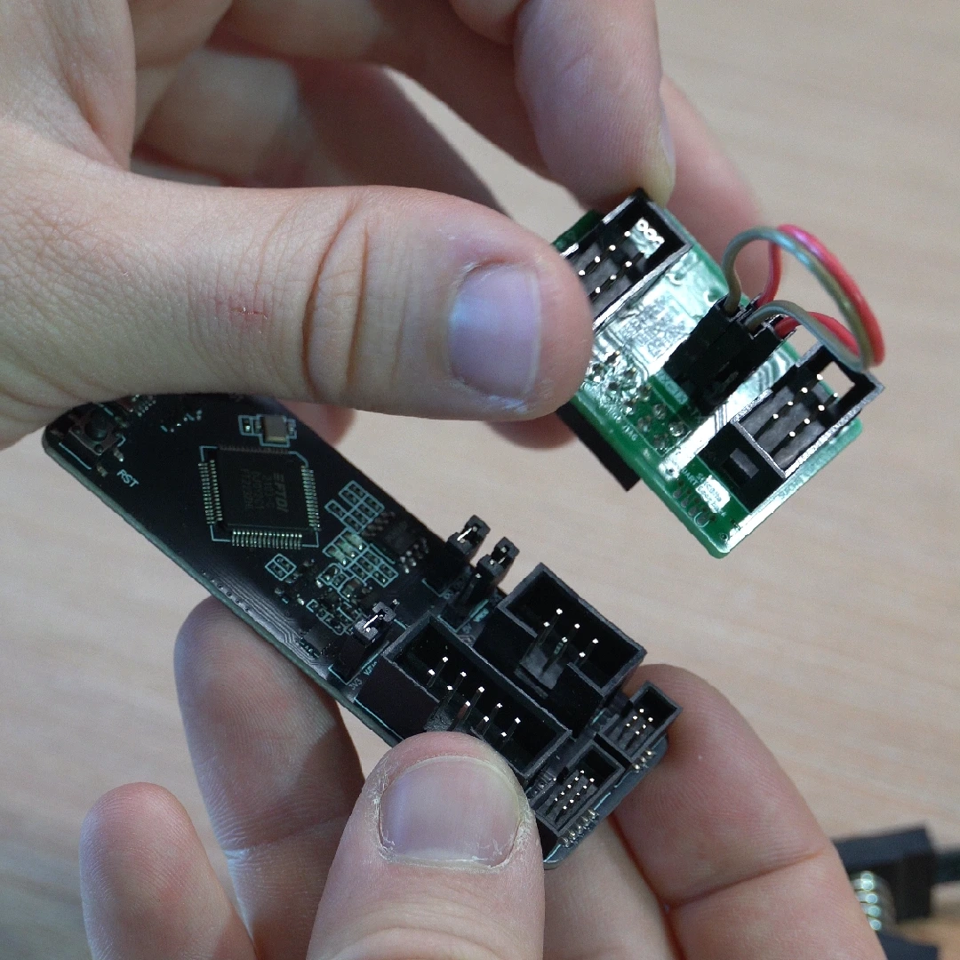
It's all powered by this little board that slots on top of an ESP32-PROG. The PROG is a generic ESP32 debugger, that contains multiple interfaces as well as the boot and reset buttons. This means I don't need to put those buttons onto my PCB; instead, I just expose those pins via the clip, and I can press them on the PROG instead. The board is just an adapter that goes between the pins on the PROG and the SOIC-8 clip.
Speaking of the clip, it's not a perfect solution out of the box. The clip is designed to grip a much wider package, while PCBs are quite thin. It doesn't quite close far enough to close all the way, so it needs a little bit of modification:
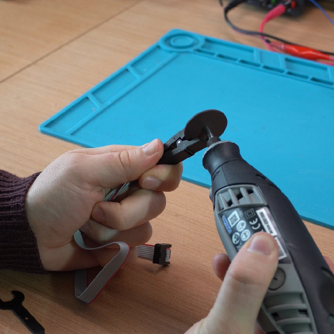
I recently picked up a Dremel and wow did this make the job go faster! The first clip I did, I filed it by hand. Doable and arguably a cleaner result, but this works great too. I would recommend pulling the spring out of the clip first to give yourself more room, then gradually grinding off some of the plastic bit by bit. You want to take off enough that it can grip the PCB, but not so much that the contacts touch each other when it's not in use.
I've been using this solution for years and I've found it to be the cheapest, smallest way to get debug access on the boards I make. The footprint of the connector itself is tiny, and because it's just pads on the board, there's no component costs! The clip doesn't grip very hard, and it's best to connect it while the debugger is unpowered. I did damage my ESP-PROG once by connecting it while live and short-circuiting it.
It's great for my one-off designs. For more mass-scale production this would get fiddly very fast, which is why pogo pin jigs are the way to go. There's also Tag Connect, which is a more professional solution. It's nice because it doesn't require the connector to be at the edge of the board, giving a bit more flexibility, but it does cost quite a bit more.
Also, the ESP-PROG plus adapter board is quite a large and cumbersome solution. But it's just a programmer, and it doesn't need to be perfect. I especially like the ability on the adapter board to swap the RX and TX around, as I definitely did get them mixed up on my first boards and this was a lifesaver.
But getting this working cost very little and it works great for me. There's a footprint available for most PCB design softwares, go check it out!