
You know what’s the biggest mood killer in the bedroom? Alright, maybe there’s plenty of situations that I’m skipping over here, but for me it would be turning on the big light, and blasting a peaceful space with the power of a small sun. That’s why I set out to add some more subtle lighting to the space, by building my own integrated hotel-style bed.
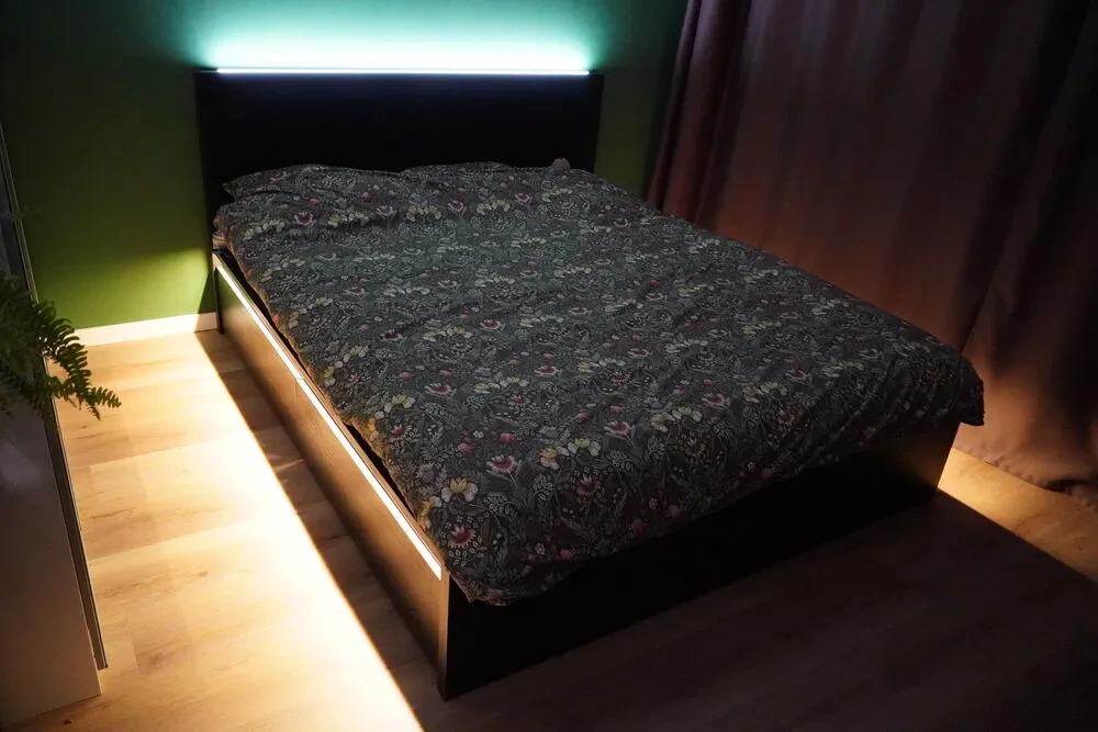
Looks cool, right? We’re skipping ahead a bit here though, let’s rewind to the beginning. It starts with the IKEA MALM. This simple, mostly solid bedframe has lasted me through many house moves, and still soldiers on to this day. With its simple, square design and plenty of integrated storage underneath, it’s everything I could ask for out of a standard IKEA product. But under its faux-wood dark exterior, it’s either chipboard or hollowed out paper. Plenty of space to add some smartness. I not only wanted to have some lighting, but also the ability to hook into the rest of my smart home, based on Home Assistant. ESPHome came as the obvious choice, allowing me to hook up lights and buttons, and have it all controlled centrally.
The requirements list
Here’s a list of my other requirements, in no particular order:
- The ability to choose the colour temperature, moving between cool white and warm white.
- Two independent lighting zones, one for each side of the bed.
- Buttons integrated into the headboard to control said lights.
- Under‑glow – let’s have some strips illuminating the floor around the bed for those late‑night bathroom breaks, among other things.
- Ethernet connectivity – I have an RJ‑45 port next to the bed and I prefer to use that instead of Wi‑Fi where possible.
- Bed presence with two zones to detect which side is occupied.
- Temperature and humidity sensing, just because I can, really…
The first item I tackled was evaluating the feasibility of fitting lighting onto the bed. I already had a lot of LED strips lying around, so I used what I had. I decided on a 24 V system: 24 V warm/cool white strips and a warm white strip running at 12 V. By connecting the left and right underglow strips in series, the total voltage became 24 V and it matched up nicely.
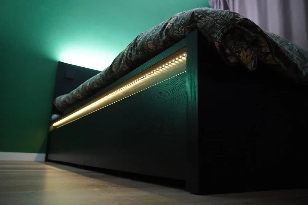
Since the warm white strip was low power, I simply stuck it to the underside of the bed. In the couple years of running it, I haven’t had any heat issues. As it’s under the bed, you won’t see the strip unless you’re lying on the ground, like this:
However, the warm/cool white strip is high power, as it needs to be bright enough to read and see things while sitting in bed. I also wanted it to run across the top of the headboard, so it would be very visible. For this, I embedded an LED profile into the top of the headboard, running along the entire length and pointing upwards. While it doesn’t shine directly on you when you’re in bed, it should be powerful enough to softly illuminate the space.
The main challenge was cutting a channel into the top of the headboard, so I turned to Marktplaats (the Dutch e‑Bay) and found a cheap router. The seller was very helpful, even providing several sets of routing bits. Money well spent. I used it to cut a channel across the top of the headboard and installed a black inset LED profile with a diffuser to conceal the LEDs underneath.
Adding the smart-ness
The cheapest method of adding ethernet to an ESPHome project that I know of is to use the ESP32-ETH01 module, easily obtained off AliExpress. It has everything you need and nothing you don’t - an ESP32, some GPIO and of course an RJ-45 jack. There’s no onboard USB serial or anything like that which is just a nice-to-have, and once you’ve got ESPHome flashed on there, all future firmware updates go over the network anyway.
This is of course not enough to power the LED strips themselves. To do that, I need a way for the ESP32 to switch on and off a 24 V line. A MOSFET will do the trick, so I picked up these nice and cheap N‑Channel 30 V 55 A MOSFETs from LCSC. While I could frankenstein something together with hacky soldering, a clean solution is preferable, so I mocked up this little PCB to mount the ESP32‑ETH01 onto:
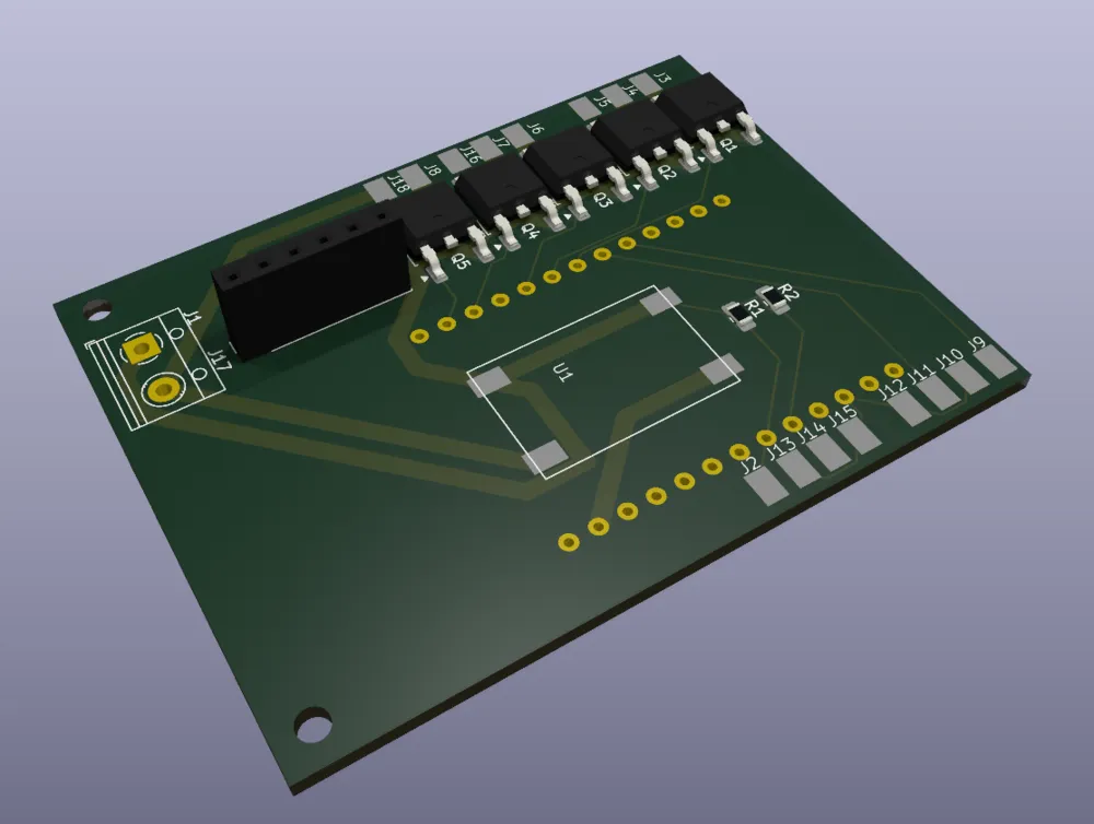
It’s missing a few details in the render, but the gist is that there’s a screw terminal on the left side (J1) that accepts the 24 V power. I use a small buck converter bought off AliExpress to provide the 5 V the board expects, soldered onto U1. There are five MOSFETs – two for each warm/cold pair on the headboard, and one for the strips under the bed.
Finally, I added a header for plugging in a BME680 breakout board. It's a quick & dirty way of getting temperature & humidity info into Home Assistant, but the reading where impacted by the fact it was sandwiched between the wall and headboard. It's since been retired, as the CTRL ONE I have in the bedroom now is able to gather much more accurate temperature, humidity and CO2 readings as a smart thermostat.
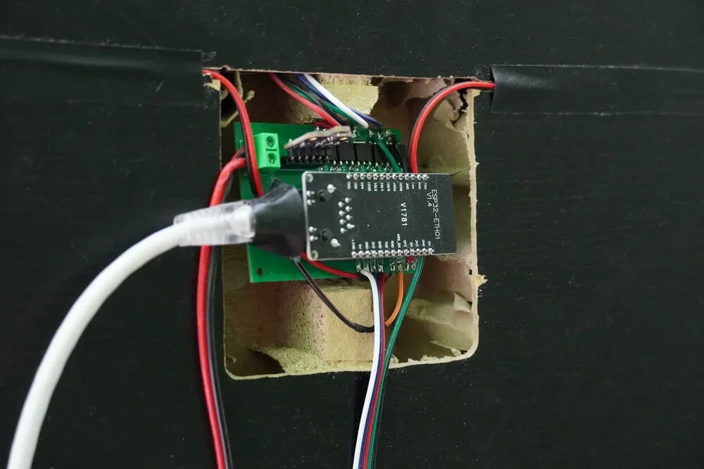
The ESP32‑ETH01 mounts upside‑down onto the pins in the centre, and there’s an array of pads to solder directly the LED wires, along with the buttons and bed presence system.
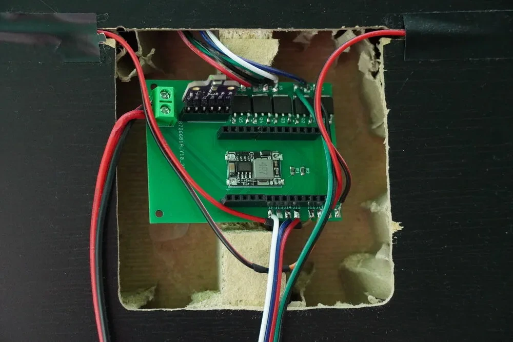
The last thing was to hack a hole into the back of the headboard. I thought this would be easy because I knew it was hollow on the inside, but I didn’t realise there was a structural support running right up the middle – that’s where I cut my hole. In the end this was a hack job; I simply suspended the PCB in the hollow area, hanging it off its wires. Once you push the bed up against the wall, all of my sins are nicely hidden. The final step is to plug in the ESP32, and we’re off to the races.
Bed presence
The idea is to sense when someone is lying on one side or the other, so automations can be built around it. I borrowed the idea from an existing product – the Bed Presence for ESPHome sensor . It does exactly what it says by using two Force‑Sensing Resistors (FSR) that run along a bed slat on each side. When a weight is applied to the mattress above, the voltage changes. Unfortunately it didn’t work straight out of the box for me, as the voltage wasn’t changing enough to reliably detect someone. That suggested the force was being transferred too evenly between the slats, so I added something to increase the load on that particular slat.
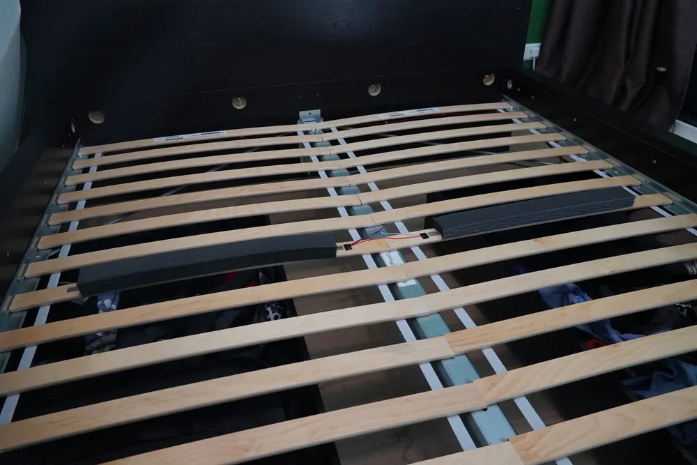
The solution turned out to be simple and elegant – I used two thick foam strips taped on top of the FSRs. Now, when someone lies on the bed, the foam compresses and transfers more force to the FSR, without noticeably altering the mattress feel.
However, here’s the thing. I knew I wanted to add this because it’s a cool thing to add - no other reason really. I very much went into this rabbithole with the intention that I would come up with ideas on how to use it in the future. Initially I tried to implement a feature where, when someone leaves the bed, it turns on the underglow at a low brightness or so for 30 seconds so you can find your way out of the room. However, during the night, if either one of us moved (hogged) the other’s side of the bed, it would detect this as someone leaving a side and turn on the lights when you’re not expecting it…
So, it works! I just can’t think of any good uses for it. One more lesson learned - it might be cool, but make sure you actually have some good uses for a sensor before you implement it. Still, nice to have for future ideas.
The buttons
The hardest part of this was trying to come up with a solution that looks nice, and is simple to find. I wanted to have more traditional-looking switches, but the problem is that a standard light-switch expects to have a cavity behind it, and also is switched between two states (on/off). Since I can also turn on the lights via Home Assistant, I want to have buttons that look like standard switches. Push-buttons are also great because you can have different combinations of presses to do different things. For me, a single press turns on the headboard light on your side of the bed, while a double press activates the underglow lighting. Via Home Assistant, I also have a long-press that can turn on the main light… That option hardly ever gets used.
As always though, AliExpress to the rescue again. These cheap wireless RF wall switches are designed to be run on a battery, and send signals to a nearby RF receiver. I figured that it was just a plastic casing, and a PCB with a button on it, so I bought just the switches.
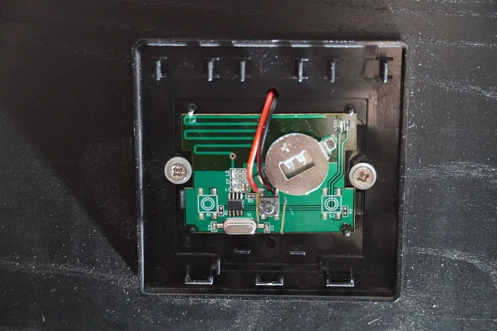
Here’s the final installed result, and it really was quite simple. By cutting the traces on the PCB leading away from the button, drilling a hole in the back and soldering my own wires to each terminal of the button, we can simply ignore the rest of the PCB and feed the button press signal straight back to the ESP32. Again, behind the headboard is a bit of a hack job; using a router, I cut a channel leading to the mainboard. Then some black electrical tape nicely covers it.
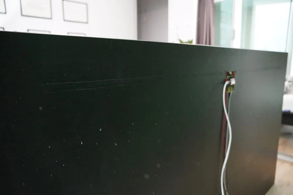
Overall though, the result is some sleek-looking buttons that match the colour of the headboard, and provide a large surface area for when you’re feeling for it at night. I’m super happy with how it looks, from the front, at least.
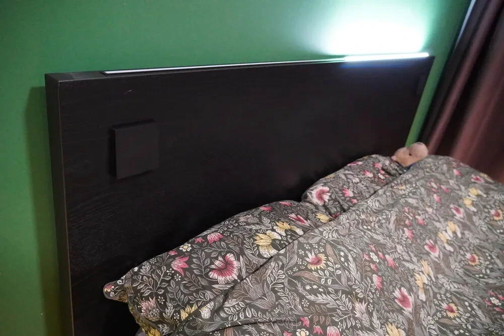
Wiring it all together
With all these pieces in place, it was time to bring it together, and bring it to life. To bring power to the operation, I bought a SANPU power supply (yes, off AliExpress, who would have guessed), and screwed it underneath the bed. Luckily for me the drawers aren’t deep enough to reach the center, so there’s plenty of space for it without causing any clearance issues.
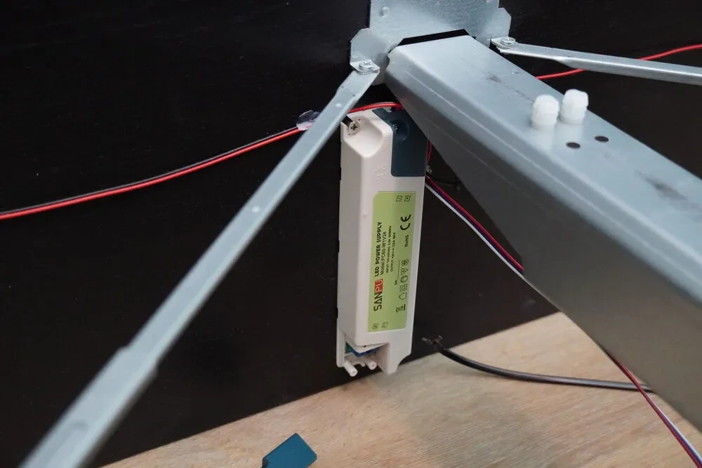
Getting the drill out, I made a hole large enough to thread both the 24 V power wires along with the FSR wires up behind the headboard, to the control board. Connecting everything, we get the final result:
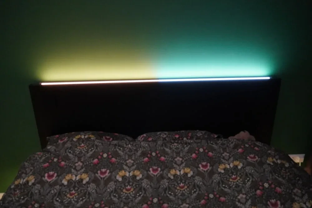
Alright, running two different colour temperatures was just for show, but the main point was to show that they’re adjustable. The super neat part is combining this with the Adaptive Lighting HACS addon for Home Assistant, allowing the lights to turn on gradually to simulate sunrise and sunset. I’ve found it really helps get me up much more naturally in the morning, and I can highly recommend this - not just for the bedroom, but for all lighting in the home.
Lessons learned
As with any new DIY project, there’s a bunch of things I learned for future endeavours, but also some things that of course I’d like to improve about this design. The base bedframe was a perfect candidate for the job, but I actually built this last year, before I moved into my current place. Future me did not like the way that past me did not include any considerations for disassembling the bedframe, as I had simply wired it up on the already assembled bed. This meant I had to cut the wires, then solder them back together later. This is why some of the wires are a little too short around the control panel, as I didn’t leave enough slack to accommodate for this. Unfortunately I have not learned from this, as I didn’t put any connectors in this time either. Next time, I guess.
Another note, the PCB is probably way too simple; I’m a beginner and don’t own an oscilloscope so there’s a bunch of noise and other things that make the LEDs glow ever so slightly even when off. Not enough to shine any light, but noticeable if you look at it. I made it in KiCad and I’ll share the design if you ask… on the condition that you improve it!
But the biggest lesson I learned was the proper implementation of the Home Approval Factor. While my partner does like and use the lights built into the bed, the indirect lights just don’t have enough light when trying to read a book. So in reality, the bed looks like this:
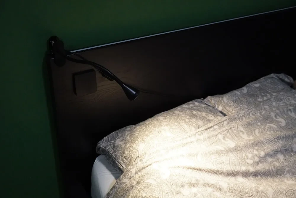
Convenience wins over aesthetics this time. Guess I know what the biggest new feature will be if I build a V2.
The code
For those interested, here’s my ESPHome config so you can take inspiration for your own projects:
esphome:
  name: bed
  friendly_name: Bed
  platformio_options:
    board_build.flash_mode: dio
  on_boot:
    then:
      - light.control:
          id: light_left
          state: off
          color_mode: COLD_WARM_WHITE
          brightness: 80%
          color_temperature: 3000 K
      - light.control:
          id: light_right
          state: off
          color_mode: COLD_WARM_WHITE
          brightness: 80%
          color_temperature: 3000 K

esp32:
  board: wt32-eth01
  framework:
    type: esp-idf

# Enable logging
# logger:

api:
  reboot_timeout: 8h
  encryption:
    key: !secret encryption_key

ota:
  - platform: esphome

ethernet:
  type: LAN8720
  mdc_pin: GPIO23
  mdio_pin: GPIO18
  clk_mode: GPIO0_IN
  phy_addr: 1
  power_pin: GPIO16

network:
  enable_ipv6: true

button:
  - platform: restart
    name: Restart
    id: restart_button
  - platform: safe_mode
    name: Restart (Safe Mode)
    id: restart_safe_mode_button

i2c:
  sda: GPIO5
  scl: GPIO17
  scan: false

sensor:
  - platform: uptime
    name: Uptime
    id: uptime_sensor
  - platform: bme680
    address: 0x77
    heater:
      duration: 0s
    temperature:
      name: Temperature
      filters:
        - sliding_window_moving_average:
            window_size: 10
            send_every: 5
        - offset: -2.5
        - delta: 0.1
    humidity:
      name: Humidity
      filters:
        - sliding_window_moving_average:
            window_size: 10
            send_every: 5
        - delta: 0.1
    pressure:
      name: Pressure
      filters:
        - sliding_window_moving_average:
            window_size: 10
            send_every: 5
        - delta: 0.1
    update_interval: 3s

  - platform: adc
    pin: GPIO32
    id: left_voltage
    update_interval: 1s
    attenuation: auto
    internal: true
    filters:
      - delta: 0.1
  - platform: adc
    pin: GPIO33
    id: right_voltage
    update_interval: 1s
    attenuation: auto
    internal: true
    filters:
      - delta: 0.1
binary_sensor:
  - platform: gpio
    pin:
      number: GPIO39
      mode:
        input: true
    name: Left Button
    id: left_button
    icon: mdi:light-switch
    disabled_by_default: true
    filters:
      - delayed_on: 10ms
    on_multi_click:
      - timing:
          - ON for 20ms to 1s
          - OFF for at least 0.2s
        then:
          - light.toggle: light_left
      - timing:
          - ON for 20ms to 1s
          - OFF for at most 1s
          - ON for 20ms to 1s
          - OFF for at least 0.2s
        then:
          - light.toggle: light_under
      - timing:
          - ON for at least 1s
        then:
          - homeassistant.event:
              event: esphome.bed_button_left_long_pressed
  - platform: gpio
    pin:
      number: GPIO36
      mode:
        input: true
    name: Right Button
    id: right_button
    icon: mdi:light-switch
    disabled_by_default: true
    filters:
      - delayed_on: 10ms
    on_multi_click:
      - timing:
          - ON for 20ms to 1s
          - OFF for at least 0.2s
        then:
          - light.toggle: light_right
      - timing:
          - ON for 20ms to 1s
          - OFF for at most 1s
          - ON for 20ms to 1s
          - OFF for at least 0.2s
        then:
          - light.toggle: light_under
      - timing:
          - ON for at least 1s
        then:
          - homeassistant.event:
              event: esphome.bed_button_right_long_pressed
  - platform: template
    name: "Left Occupancy"
    device_class: occupancy
    lambda: |-
      return id(left_voltage).state > 2.0;
    filters:
      - delayed_off: 2s
    on_release:
      - if:
          condition:
            switch.is_on: leave_light
          then:
            - light.turn_on:
                id: light_under
            - delay: 10s
            - light.turn_off:
                id: light_under
                transition_length: 5s
  - platform: template
    name: "Right Occupancy"
    device_class: occupancy
    lambda: |-
      return id(right_voltage).state > 1.0;
    filters:
      - delayed_off: 2s
    on_release:
      - if:
          condition:
            switch.is_on: leave_light
          then:
            - light.turn_on:
                id: light_under
            - delay: 10s
            - light.turn_off:
                id: light_under
                transition_length: 5s

switch:
  - platform: template
    id: leave_light
    name: Leave Light
    optimistic: true
    icon: mdi:lightbulb-auto
    restore_mode: RESTORE_DEFAULT_ON

output:
  - platform: ledc
    id: warm_white_output_left
    frequency: 9765Hz
    pin:
      number: GPIO4
  - platform: ledc
    id: white_output_left
    frequency: 9765Hz
    phase_angle: 72
    pin:
      number: GPIO2
  - platform: ledc
    id: warm_white_output_right
    frequency: 9765Hz
    phase_angle: 144
    pin:
      number: GPIO12
  - platform: ledc
    id: white_output_right
    frequency: 9765Hz
    phase_angle: 216
    pin:
      number: GPIO14
  - platform: ledc
    id: output_under
    frequency: 9765Hz
    phase_angle: 288
    pin:
      number: GPIO15

light:
  - platform: cwww
    id: light_left
    name: Left Light
    warm_white: warm_white_output_left
    cold_white: white_output_left
    cold_white_color_temperature: 6500 K
    warm_white_color_temperature: 2400 K
  - platform: cwww
    id: light_right
    name: Right Light
    warm_white: warm_white_output_right
    cold_white: white_output_right
    cold_white_color_temperature: 6500 K
    warm_white_color_temperature: 2400 K
  - platform: monochromatic
    id: light_under
    name: Under Light
    output: output_under
I use affiliate links for products that I use in my blog posts. The products themselves are chosen based on their merit and quality, and I buy them with my own money. If you get inspired by what I show, I'd appreciate you ordering via them so I get a small kickback, with no extra cost to you. Thanks for reading!